Installation
11
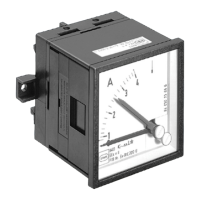
Ammeter Version 8403/2 and 8405/2
8 Installation
8.1 Mains connection
• Make the cable connections very carefully.
• The conductor insulation must reach to the terminal. The conductor itself must not be
damaged (nicked) when removing the insulation.
• Ensure that the maximum permissible conductor temperatures are not exceeded by
suitable selection of cables and means of running them.
When termination sleeves are fitted, they must be gas-tight and applied with a suitable
tool.
Please also take note of the information on terminals in the Technical data section.
9 Commissioning
Before commissioning, ensure that:
• the ammeter has been mounted according to the directions
• the ammeter is not damaged
• connections have been correctly made
• all screws and nuts are fully tightened.
10 Using the ammeter
10.1 Zero point setting
If, after fitting the ammeter, the black pointer is no longer in the zero position at 0 A, the
zero point setting can be adjusted.
Pre-requisites are that the ammeter is fitted and disconnected from the supply
Zero point setting
• Set the pointer to 0 by turning the screw at bottom right on the ammeter face.
10.2 Measured value comparison
• To set, for example, a Reference Value, move the red pointer (upper screw on amme-
ter face).
10.3 Changing measuring range
• The scale on 1 A and 5 A ammeters with instrument transformers can be matched
easily and quickly to measuring range in situ by inserting the appropriate scale plate
from the side.
Under no circumstances should the scale of direct-reading ammeters be changed!