STEP 3
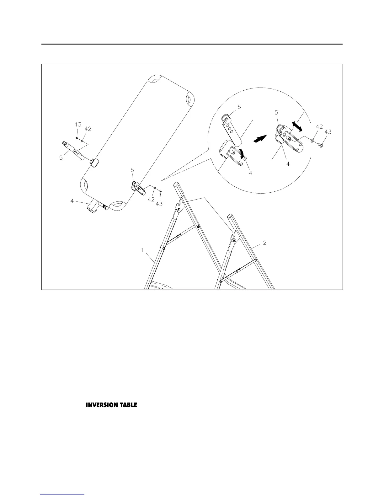
Slide the bottom of the two PIVOT ARMS(5) into the brackets located at each side of the MAIN FRAME(4).
Align the desired hole on the arm with the peg on the bracket, and insert the peg into the hole to lock the
PIVOT ARMS(5) in position. Then secure the PIVOT ARMS(5) on the pegs with BUTTON HEAD
BOLTS(M6 x 8mm)(43) and LARGE WASHERS(M6)(42).
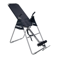
PIVOT ARM ADJUSTMENT:
There are three adjustment holes on the PIVOT ARMS(5) allowing you to position the MAIN FRAME(4)
at three different heights. The lowest hole will allow the least amount of inversion angle. The top hole will
allow the greatest amount of inversion angle.
CAUTION:
STEP 4
Attach the MAIN FRAME(4) onto the REAR FRAME(2) by sliding the slots in the ends of the two PIVOT
ARMS(5) into the slots on the REAR FRAME(2).
ASSEMBLY INSTRUCTIONS
7
Use the lowest holes in the
PIVOT ARMS(5) until you become familiar with the
.
Both
PIVOT ARMS(5) must be adjusted to the same hole. Trying to adjust the PIVOT
ARMS(5) to different positions could cause damage to the machine, and injury to the user.
SLOTS
1.
2.