ASSEMBLY INSTRUCTIONS
9
1.
2.
BUCKLE
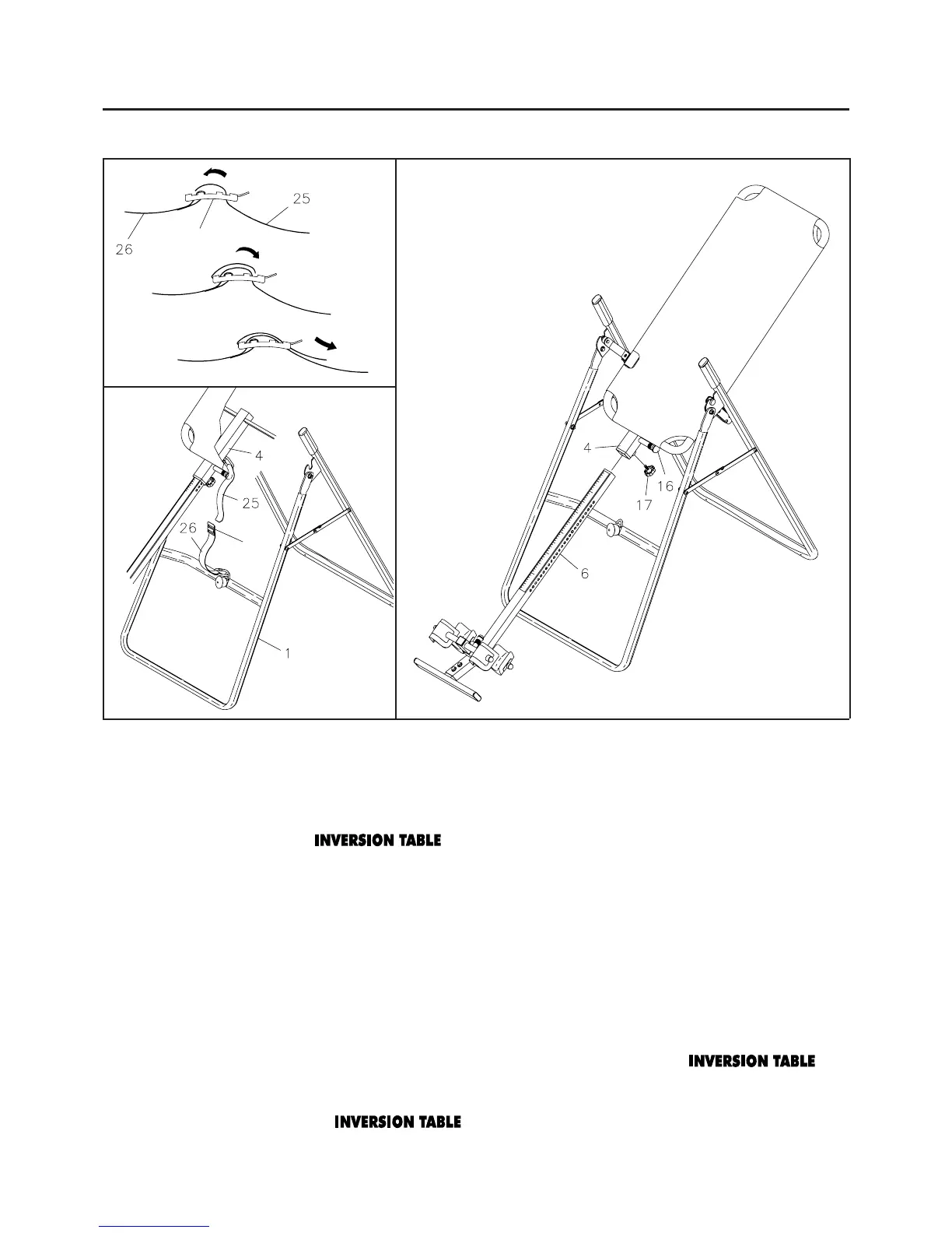
STEP 8
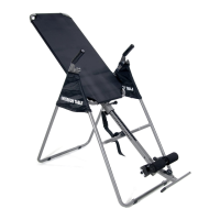
Install the HEIGHT ADJUSTMENT BEAM(6) into MAIN FRAME(4) by pulling the LARGE SPRING
PIN(16) on the MAIN FRAME(4) and inserting the HEIGHT ADJUSTMENT BEAM(6) as shown. For
added safety, thread the
LOCKING KNOB(17) into back side of the MAIN FRAME(4).
WARNING: Do not use the until you have verified your height setting. Failure to use
the proper height setting can result in difficulty recovering from the decline position. See
HEIGHT ADJUSTMENT instructions on page 10.
STEP 9
Attach the NYLON STRAP(25) onto the BUCKLE on the end of the BUCKLE STRAP(26) by inserting
the end of the strap up through the bottom of the buckle, as shown in the illustration 1.
STEP 10
Hook the end of the NYLON STRAP(25) onto the loop on the back of the MAIN FRAME(4). Hook the
end of the
BUCKLE STRAP(26) onto the loop on the FRONT FRAME(1).
NOTE: The NYLON STRAPS are used to control the decline angle of the . For
a steeper decline angle, lengthen the straps. For a lessor decline angle, shorten the straps.
Make sure these NYLON STRAPS are tight in the buckle and check the decline angle
before using the .
A.
C.
B.
BUCKLE