Do you have a question about the Stamina Viper VG1500 and is the answer not in the manual?
General guidelines for setting up the system and performing pre-use checks on cables and components.
Recommendations for consulting a physician, choosing workouts, and safe usage practices.
Crucial warning advising medical consultation before starting any exercise program.
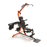
Familiarize yourself with the labeled parts of the VG1500 Leverage System before proceeding.
Lists the tools necessary for the assembly of the VG1500 Leverage System.
Important notice explaining how to measure the length of bolts and screws.
Instruction to unpack and verify all hardware components are present before assembly.
General instructions for clearing a space, reading steps, and contacting support for missing parts.
Attaching the foot plate to the base frame using specified bolts.
Connecting the base frame, rear stabilizer, and rear support with bolts and nuts.
Attaching the lower upright to the base frame and rear stabilizer.
Connecting the lever arm to the lower upright, ensuring smooth pivoting.
Sliding and locking weight collars onto the lever arm.
Routing the cable through uprights and attaching pulleys with specified hardware.
Ensures pulleys rotate freely by not overtightening specific bolts.
Inserting uprights and securing cables and uprights with specified bolts and washers.
Attaching the slider support to the lower upright, ensuring smooth pivoting.
Installing the adjustment bar into the slider support using a spring pin.
Connecting the back support to the lower upright and adjustment bar.
Attaching the seat frame to the lower upright with specified hardware.
Connecting the leg lift to the seat frame using specific bolts.
Routing cable for leg lift and attaching arm brace to lower upright.
Attaching foam supports to both sides of the lower upright.
Mounting the head rest and back cushion onto the back support.
Attaching seat cushion and inserting/locking seat post into seat frame.
Identifying and attaching left/right leverage arms with washers and nuts.
Attaching weight bars to leverage arms and securing with collars and knobs.
Assembling handlebars to leverage arms, including bearings and securing bolts.
Sliding foam rollers onto support tubes and securing them.
Attaching foam rollers to foam supports.
Connecting the short cable to the upright using a pulley and quick link.
Attaching the lat bar to the cable, using chains for specific exercises.
Connecting straight bar handle and ankle cuff to the cable via quick links and chains.
Attaching the ab curl strap to the short cable for specific exercises.
Keep the VG1500 Leverage System in a clean, dry place for storage.
Ensuring safety and integrity through regular checks of labels, components, and cables.
Preparing muscles for exercise by raising heart rate and performing stretches.
Illustrations and instructions for various stretches to improve flexibility.
Returning the body to a resting state after exercise to lower heart rate.
Details the warranty period for parts and frame, and conditions of coverage.
Specifies what is not covered by the warranty and liability limitations.
Outlines legal rights, implied warranties, and jurisdictional restrictions.
Visual representation of all components with corresponding diagram numbers.
A list of all parts with their diagram numbers, names, and quantities.
Continuation of the parts list, detailing further components and their specifications.
A section for general notes or remarks related to the product.
Contact information for customer service and a form for ordering parts via fax or mail.
| Resistance | Magnetic |
|---|---|
| Resistance Levels | 8 |
| Monitor | LCD |
| Weight Capacity | 250 lbs |
| Drive System | Belt |