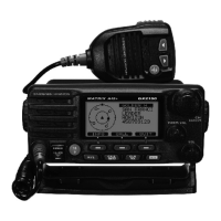
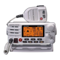
EasyManua.ls Logo

Standard Horizon MATRIX Series User Manual

Standard Horizon MATRIX Series
144 pages
To Next Page IconTo Next Page
Page #1 background imageLoading...
Page #1 background image
MATRIX SERIES
GX2000 and GX2150
25 Watt VHF/FM
Marine Transceivers
Owner's Manual
GX2000: AIS support with external AIS receiver or transponder
GX2150:IntegrateddualchannelAIS(AutomaticIdenticationSystem)receiver
GX2150: 4800 or 38400 NMEA baud rate selection for plotters with 1 NMEA port
GX2150:AbletousePAorFogsignalingwhenonAISdisplay
TrueandMagneticbearingselectiononAISdisplay
AIStargetdisplayincludesMMSI,Callsign,ShipName,BRG,DST,SOG&COG
ContactClassAorBAISShipwithDSC
ProgrammableCPAorTCPAcollisionavoidancealarms
ITUClassDDSC(IndependentChannel70receiverbuilt-in)
Navigationinformation(LAT/LONG,SOG,COG)informationshownondisplay
NavigatetoaDSCDistressPosition
Enter,SaveandNavigatetoawaypointwithcompasspage
80dBcommercialgradereceiver
AutomaticDSCPositionPollrequesttoupto4separatevessels
E2O(Easytooperate)menusystemwithuserprogrammablesoftkeysonradio
GPSCompass,WaypointandGPSstatuspages
SubmersibleJIS-7/IPX-7rating(3.3feetfor30mins)
GX2150: 30WattPA/Loudhailerwithpreprogrammedfog signals andlisten-back
facility
ClearVoicenoisecancellingmicrophonewithchannelselectorand16/9key
CapableofconnectingtoaSecondStationRemote-AccessMicrophoneCMP31
IntercombetweenradioandRAM3+microphone
Versatileuser-programmablescanning,priorityscanandDualWatch
OversizedrotaryCHknobwithpushtoenter,backlitdisplayandkeys
VoiceScrambler(optional)
Local/Distanceattenuator
GX2150requiresconnectiontoexternalGPSor
GX2000requiresconnectiontoexternalGPSandAISreceiverortransponder
MATRIX AIS+ GX2150MATRIX GX2000

Table of Contents

Questions and Answers:

Standard Horizon MATRIX Series Specifications

General IconGeneral
Waterproof RatingIPX7
Power Output25W
Display TypeLCD
DimensionsVaries by model
WeightVaries by model
GPSYes
DSCYes
DSC CapabilityYes
Output Power25W

Summary

Quick Reference Guide

1 GENERAL INFORMATION

2 PACKING LIST

3 OPTIONAL ACCESSORIES

4 ONLINE WARRANTY REGISTRATION (in USA or Canada only)

5 GETTING STARTED

5.1 PROHIBITED COMMUNICATIONS

Outlines FCC restrictions on marine radio transmissions, including false distress and profane language.

5.2 ABOUT VHF RADIO

Explains VHF radio frequencies, range characteristics, and factors affecting transmission distance.

5.3 SELECTING AN ANTENNA

Discusses antenna gain and selection criteria for marine VHF radio installations.

5.4 COAXIAL CABLE

5.5 DISTRESS AND HAILING (CHANNEL 16)

5.6 CALLING ANOTHER VESSEL (CHANNEL 16 OR 9)

5.7 MAKING TELEPHONE CALLS

5.8 BRIDGE CHANNELS 13 AND 67

5.9 AUTOMATED RADIO CHECK SERVICE

5.10 WHAT IS THE RANGE FOR AIS RECEIVERS?

6 INSTALLATION

6.1 SAFETY / WARNING INFORMATION

Highlights safety precautions and FCC RF exposure requirements for radio installation.

6.2 LOCATION

Advises on choosing an optimal mounting location for the radio, considering compass deviation.

6.3 MOUNTING THE RADIO

Instructions for mounting the radio using supplied or optional brackets.

6.4 ELECTRICAL CONNECTIONS

Details how to connect power, antenna, and accessories safely, including fuse replacement.

6.5 ACCESSORY CABLES

Explains connections for external speakers, GPS, and AIS devices for GX2000 and GX2150.

6.6 CHECKING GPS CONNECTIONS

Verifies the proper connection and function of the GPS unit with the radio.

6.7 CHANGING THE GPS TIME

Describes how to set the radio's time based on GPS input or UTC.

6.8 CHANGING THE TIME LOCATION

Allows selection between UTC and local time display based on the time zone.

6.9 CHANGING THE TIME FORMAT

Sets the time display format to either 12-hour or 24-hour.

6.10 CHANGING COG TO TRUE OR MAGNETIC

Configures Course Over Ground and Bearing display to show magnetic or true headings.

6.11 OPTIONAL CMP31 (RAM3+) INSTALLATION

Instructions for installing the CMP31 (RAM3+) remote microphone accessory.

7 CONTROLS AND INDICATORS

7.1 FRONT PANEL

Describes the physical buttons, knobs, and displays on the transceiver's front panel.

7.2 REAR PANEL

Details the ports and connectors located on the back of the unit.

7.3 MICROPHONE

Explains the functions of the microphone buttons and its ClearVoice noise reduction feature.

8 BASIC OPERATION

8.1 RECEPTION

How to receive signals, adjust squelch, and select channels for listening.

8.2 TRANSMISSION

Steps for transmitting voice messages, including FCC requirements.

8.3 TRANSMIT TIME - OUT TIMER (TOT)

Explains the function and limitation of the Transmit Time-Out Timer.

8.4 SIMPLEX/DUPLEX CHANNEL USE

Information on simplex and duplex channel operations and their correct usage.

8.5 DISPLAY TYPE

How to change the radio's display screen to various modes like NORMAL, AIS, or COMPASS.

8.6 USA, INTERNATIONAL, AND CANADA MODE

Setting the transceiver for different regional channel regulations (USA, INT, CAN).

8.7 NOAA WEATHER CHANNELS

Accessing and using NOAA weather channels and alerts for weather information.

8.8 DUAL WATCH (TO CHANNEL 16)

How to monitor Channel 16 simultaneously with another selected channel.

8.9 SCANNING

Setting up and using memory and priority scanning modes for channels.

8.10 PRESET CHANNELS (0 ~ 9): INSTANT ACCESS

Programming and using instant access preset channels for quick channel selection.

8.11 PA/FOG OPERATION

Using the hailer and fog horn functions with optional PA horns.

8.12 INTERCOM OPERATION

Facilitates communication between the main unit and a remote microphone.

8.13 VOICE SCRAMBLER

Information on installing and using the optional CVS2500 voice scrambler for secure communication.

8.14 DEMO MODE

Explains the demo mode for sales demonstrations and product showcasing.

9 DIGITAL SELECTIVE CALLING (DSC)

9.1 GENERAL

Overview of the DSC system, its purpose in maritime safety, and operational range.

9.2 MARITIME MOBILE SERVICE IDENTITY (MMSI)

Explains MMSI and provides instructions on how to program it into the radio.

9.2.1 What is an MMSI?

Definition and purpose of the Maritime Mobile Service Identity number.

9.2.2 Programming the MMSI

Step-by-step guide to entering the MMSI number into the radio, with warnings.

9.3 DSC DISTRESS CALL

Procedures for transmitting and receiving DSC distress alerts, including GPS position.

9.3.1 Transmitting a DSC Distress Call

Detailed steps for sending a DSC distress alert, requiring MMSI and optional GPS.

Transmitting a DSC Distress Alert with Nature of Distress

How to specify the nature of distress (e.g., Fire, Flooding) when sending an alert.

Transmitting a DSC Distress Alert with Manual Position of Input

Manually entering position data before sending a DSC distress alert if GPS is not connected.

Pausing a DSC Distress Call

How to temporarily suspend retransmission of an ongoing DSC distress call.

Canceling a DSC Distress Call

Procedure to send a message to cancel a previously sent distress call.

9.3.2 Receiving a DSC Distress Call

Steps for handling an incoming DSC distress call, including alarms and acknowledgments.

9.4 ALL SHIPS CALL

Contacting all vessels with DSC for urgency or safety messages.

9.4.1 Transmitting an All Ships Call

Steps for sending an All Ships call with designated urgency or safety.

9.4.2 Receiving an All Ships Call

How to acknowledge and handle incoming All Ships calls, including automatic channel switching.

9.5 INDIVIDUAL CALL

Features for contacting individual vessels via DSC, including directory setup.

9.5.1 Setting up the Individual / Position Call Directory

Programming vessel names and MMSIs for individual DSC calls and position requests.

9.5.2 Setting up the Individual Call Reply

Configuring automatic or manual replies to DSC individual calls.

9.5.3 Enabling the Individual Call Acknowledgment

Configures the radio's response for individual call acknowledgments ('Able' or 'Unable').

9.5.4 Transmitting an Individual Call

Steps to initiate an individual DSC call using the directory or manual entry.

Individual Call by Manually Entering a MMSI

Contacting a vessel by manually entering its MMSI without storing it.

9.5.5 Receiving an Individual Call

How the radio handles incoming individual DSC calls automatically or manually.

9.5.6 Setting up the Individual Call Ringer

Adjusts the duration of the incoming DSC individual call alert.

DSC Beep Settings

Enabling or disabling DSC call alert beeps for individual calls.

9.6 GROUP CALL

Features for contacting groups of vessels via DSC for coordinated communication.

9.6.1 Setting up a Group Call

Programming group MMSIs into all DSC VHF radios for coordinated communication.

Group Call Directory Setup

Steps to add and manage group call entries in the directory.

9.6.2 Transmitting a Group Call

Initiating a group call using the programmed directory for communication.

Group Call by Manually Entering an MMSI

Tracking a group by manually entering the group MMSI.

9.6.3 Receiving a Group Call

How the radio handles incoming group DSC calls and related options.

9.6.4 Setting up the Group Call Ringer

Adjusts the duration of the incoming DSC group call alert.

9.7 POSITION REQUEST

Requesting vessel positions from other DSC-equipped vessels.

9.7.1 Setting up a Position Request Reply

Configuring automatic or manual replies to incoming DSC position requests.

9.7.2 Transmitting a Position Request to Another Vessel

Initiating a position request using the directory or manual MMSI entry.

9.7.3 Receiving a Position Request

Handling incoming DSC position requests from other vessels.

9.7.4 Setting up a Position Request Ringer

Adjusts the duration of the incoming DSC position request alert.

9.8 POSITION REPORT

Sending your vessel's position to another vessel via DSC.

9.8.1 Transmitting a DSC Position Report Call

Steps to send a DSC position report using the directory or manual MMSI.

DSC Position Report Call Manually Entering an MMSI

Sending a position report by manually entering the target's MMSI.

9.8.2 Receiving a DSC Position Report Call

How the radio handles incoming DSC position reports from other vessels.

9.8.3 Navigating to a Position Report

Using the compass display to navigate to a received position report.

9.8.4 Stopping Navigation to a Position Report

Procedure to exit navigation mode to a waypoint after a position report.

9.8.5 Saving a Position Report as a Waypoint

Storing a received position report as a waypoint in the radio's memory.

9.8.6 Navigating to a Saved Waypoint

Using the compass display to navigate to a saved waypoint.

9.8.7 Setting up a Position Report Ringer

Adjusts the duration of the incoming DSC position report alert.

9.9 MANUAL INPUT OF A GPS LOCATION (LAT/LON)

Manually entering GPS coordinates (latitude/longitude) for DSC transmissions.

9.10 AUTO POS POLLING

Setting up automatic polling to track vessel positions from the directory.

9.10.1 Setting up the Polling Time Interval

Configuring the time interval between automatic position requests.

9.10.2 Selecting Stations to be Automatically Polled (Tracked)

Choosing specific stations from the directory for automatic position polling.

9.10.3 Enabling/Disabling Auto Pos Polling

Activating or deactivating the automatic position polling feature.

9.11 DSC TEST

Performing test calls to verify DSC functionality with other equipped vessels.

9.11.1 Programming MMSI into Individual Directory

Referencing procedure for adding MMSI to directory for DSC tests.

9.11.2 DSC Test call by using Individual/Position Directory

Executing a DSC test call using stored contact information.

9.11.3 DSC Test Call by Manually Entering an MMSI

Performing a DSC test call by manually entering the target's MMSI.

9.12 POLLING CALL

Capability to track another vessel's position by initiating a polling call.

9.12.1 Transmitting a Polling Call to Another Vessel

Initiating a call to request another vessel's position.

Polling Call by Manually Entering an MMSI

Tracking a vessel by manually entering its MMSI.

9.12.2 Receiving a Polling Call

How the radio handles incoming polling calls.

9.13 DSC LOG OPERATION

Managing and reviewing call logs, including transmitted and received calls.

9.13.1 Reviewing and Resending a Transmitted Logged Call

Checking and retransmitting previously sent calls from the log.

9.13.2 Reviewing a Logged DSC Distress Call

Examining details of received DSC distress calls from the log.

9.13.3 Reviewing Other Logged Calls

Viewing details of other logged calls like individual, group, or position reports.

9.13.4 Deleting a Call from the DSC Log Directory

Removing entries from the DSC log for management.

10 GENERAL SETUP

10.1 DISPLAY

Options for selecting additional screen displays beyond the default.

10.2 LOCAL DISTANCE RECEIVER ATTENUATOR

Adjusting receiver sensitivity to reduce interference from strong local signals.

10.3 DIMMER ADJUSTMENT

Controls the backlight intensity of the display and keys.

10.4 DISPLAY CONTRAST

Adjusts the display contrast for optimal visibility.

10.5 TIME OFFSET

Sets the local time offset relative to UTC based on GPS input.

10.6 TIME AREA

Allows selection between UTC and local time display.

10.7 TIME DISPLAY

Configures the time display format to 12-hour or 24-hour.

10.8 UNIT OF MEASURE

Selects units for speed, distance, and altitude displays.

10.9 MAGNETIC

Configures COG and BRG displays to show magnetic or true headings.

10.10 NMEA DATA IN/OUT

Sets NMEA 0183 baud rates for GPS input and DSC/AIS output.

10.11 KEY BEEP

Adjusts the volume level for key press tones.

10.12 FOG ALERT TONE FREQUENCY

Sets fog horn signal frequencies based on vessel size.

10.13 STATION NAME

Assigns custom names to the radio or remote microphone units.

10.14 SOFT KEYS

Customizes the functions assigned to the programmable soft keys.

11 CHANNEL FUNCTION SETUP

11.1 CHANNEL GROUP

Selects the channel group for USA, Canada, or International use.

11.2 SCAN MEMORY

Allows storing channels for scanning purposes.

11.3 SCAN TYPE

Selects between Memory Scan and Priority Scan modes.

11.4 SCAN RESUME

Sets the delay time before scanning resumes after a transmission.

11.5 PRIORITY CHANNEL

Designates a specific channel as the priority channel for scanning.

11.6 WEATHER ALERT

Enables or disables the NOAA Weather Alert function.

11.7 CHANNEL NAME

Assigns custom names to channels for easier identification.

11.8 SCRAMBLER SETUP

Configures the optional voice scrambler settings.

12 DSC SETUP

12.1 INDIVIDUAL DIRECTORY

Stores vessel names and MMSIs for individual DSC calls and position requests.

12.2 INDIVIDUAL REPLY

Sets automatic or manual replies to individual DSC calls.

12.3 INDIVIDUAL ACKNOWLEDGMENT

Configures radio response for individual call acknowledgments ('Able' or 'Unable').

12.4 INDIVIDUAL RINGER

Adjusts the duration of the incoming DSC individual call alert.

12.5 GROUP DIRECTORY

Stores group MMSIs for coordinated communication.

12.6 POSITION REPLY

Configures automatic or manual replies to position requests.

12.7 DSC BEEP

Enables or disables DSC call alert beeps for various call types.

12.8 AUTO CHANNEL SWITCH TIME

Sets the time for automatic channel switching to Channel 16 upon DSC alerts.

12.9 NO ACTION TIMER ON MENU OPERATION

Configures the timeout period for menu inactivity.

12.10 NO ACTION TIMER ON DSC OPERATION

Sets the timeout for inactivity during DSC operations.

12.11 NO ACTION TIMER ON DISTRESS OPERATION

Sets the timeout for inactivity during distress operations.

13 AUTOMATIC IDENTIFICATION SYSTEM (AIS)

13.1 GENERAL

Overview of the Automatic Identification System and its purpose in collision avoidance.

13.2 AIS OPERATION

How to display and interpret AIS targets on the radio screen.

13.2.1 AIS Range

Adjusting the display range for AIS targets on the screen.

13.2.2 Transmitting an Individual Call to an AIS Ship

Making DSC individual calls to AIS targets for communication.

13.2.3 Receiving an AIS-SART Signal

Handling distress signals from AIS-SART devices.

13.3 AIS/COMPASS SETUP

Configuring AIS compass display orientation and activation range.

13.3.1 Direction

Setting the AIS compass display to Course Up or North Up.

13.3.2 Activation Range

Setting the detection range for AIS targets.

13.3.3 CPA Alarm

Setting up alarms for Closest Point of Approach with AIS targets.

13.3.4 TCPA Alarm

Setting up alarms for Time to Closest Point of Approach with AIS targets.

13.3.5 Display Range

Setting the range rings displayed on the AIS screen.

14 WAYPOINTS

14.1 MARKING A POSITION

Saving the vessel's current position as a waypoint.

14.2 ADDING A WAYPOINT

Manually entering and saving waypoint details like name and coordinates.

14.3 EDITING A WAYPOINT

Modifying previously entered waypoint information.

14.4 DELETING A WAYPOINT

Removing waypoints from the radio's memory.

14.5 SAVING A DSC POSITION CALL AS A WAYPOINT

Storing a received DSC position call as a waypoint in memory.

14.6 NAVIGATING TO A SAVED WAYPOINT

Using the compass display to navigate to a saved waypoint.

14.7 STOPPING NAVIGATION TO A WAYPOINT

Procedure to exit navigation mode to a waypoint.

14.8 SELECTING THE WAYPOINT RANGE

Setting the display range for waypoints on the screen.

15 CMP31 (RAM3+) REMOTE MIC OPERATION

15.1 REMOTE MIC CONTROLS

Identifies and describes the functions of the CMP31 remote microphone controls.

15.2 ASSIGNING SOFT KEYS

Customizes soft key functions for the remote microphone.

16 MAINTENANCE

16.1 REPLACEMENT PARTS

Lists commonly requested replacement parts and their ordering information.

16.2 FACTORY SERVICE

Contact information for obtaining professional repair services.

16.3 TROUBLESHOOTING CHART

A guide to diagnosing and resolving common transceiver issues.

17 CHANNEL ASSIGNMENTS

18 WARRANTY

19 RESET PROCEDURES

19.1 MEMORY CLEAR

Steps to clear scan and preset memory contents.

19.2 MICROPROCESSOR RESETTING

Procedure to reset radio settings to factory defaults, excluding certain data.

20 SPECIFICATIONS

20.1 GENERAL

General specifications including channels, voltage, and dimensions.

20.2 TRANSMITTER

Technical details of the transceiver's transmitter performance.

20.3 RECEIVER (for Voice and DSC)

Receiver specifications for voice and DSC communications.

20.4 RECEIVER (for AIS)

Receiver specifications for AIS signal reception.

20.5 NMEA INPUT/OUTPUT

NMEA 0183 data configuration for GPS input and DSC/AIS output.

20.6 DIMENSIONS

Physical measurements of the GX2000 and GX2150 units.

21 FCC RADIO LICENSE INFORMATION

21.1 STATION LICENSE

Details on FCC ship station license requirements for vessels.

21.2 RADIO CALL SIGN

Guidance on using boat registration numbers for identification.

21.3 CANADIAN SHIP STATION LICENSING

Information on licensing requirements for vessels in Canada.

21.4 FCC / INDUSTRY CANADA INFORMATION

Technical data required for FCC and Industry Canada license applications.

22 FCC NOTICE

Related product manuals