ENGLISH
12
• Air supply hoses will have a minimum working e ective pressure rating of 150% of the maximum pressure
produced in the system or 10 bar, whichever is the highest.
• Air hoses must be oil resistant, have an abrasion resistant exterior and be armoured where operating
conditions may result in hoses being damaged.
• All air hoses MUST have a minimum bore diameter of 6.4 millimetres.
• Check for air leaks. If damaged, hoses and couplings must be replaced by new items.
• If there is no lter on the pressure regulator, bleed the airline to clear it of accumulated dirt or water before
connecting air hose to the tool.
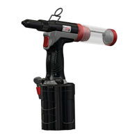
3.3 PRINCIPLE OF OPERATION
CAUTION - CORRECT SUPPLY PRESSURE IS IMPORTANT FOR PROPER FUNCTION OF THE INSTALLATION
TOOL. PERSONAL INJURY OR DAMAGE TO EQUIPMENT MAY OCCUR WITHOUT CORRECT PRESSURES.
THE SUPPLY PRESSURE MUST NOT EXCEED THAT LISTED IN THE PLACING TOOL SPECIFICATION
Item numbers in bold refer to the components in gures 1 & 2 and the tables on page 10.
When the pneumatic hose is connected to the placing tool, the pull and return cycles of the tool are
controlled by depressing and releasing the trigger (6) located in the handle.
• Air supply must be disconnected.
• Connect the appropriate nose equipment as described on page 9.
• Connect the pneumatic hose to the air on/o valve (7).
• Connect the pneumatic hose mains air supply.
• Switch on the mains supply to the tool by sliding the air on/o valve (7) to the up position.
• Air is now be supplied to the tool and the vacuum system is in operation.
• Pull and release the trigger (6) a few times to the full stroke of the tool to check operation. Observe action
of tool. Check for uid and/or air leaks.