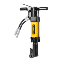
BR87 User Manual ◄ 11
The recommended hose size is .500 inch/12 mm I.D. up to 50 ft/15 m long and .625 inch/16 mm I.D. minimum up
to 100 ft/30 m.
PRE-OPERATION PROCEDURES
CHECK POWER SOURCE
1. Using a calibrated owmeter and pressure gauge, check that the hydraulic power source develops a ow of 7-9
GPM/26-34 LPM at 1500-2000 psi/105-140 bar. Proper ow and pressure maintain proper tool speed.
2. Make certain the hydraulic power source is equipped with a relief valve set to open at 2100-2250 psi/145-155
bar maximum.
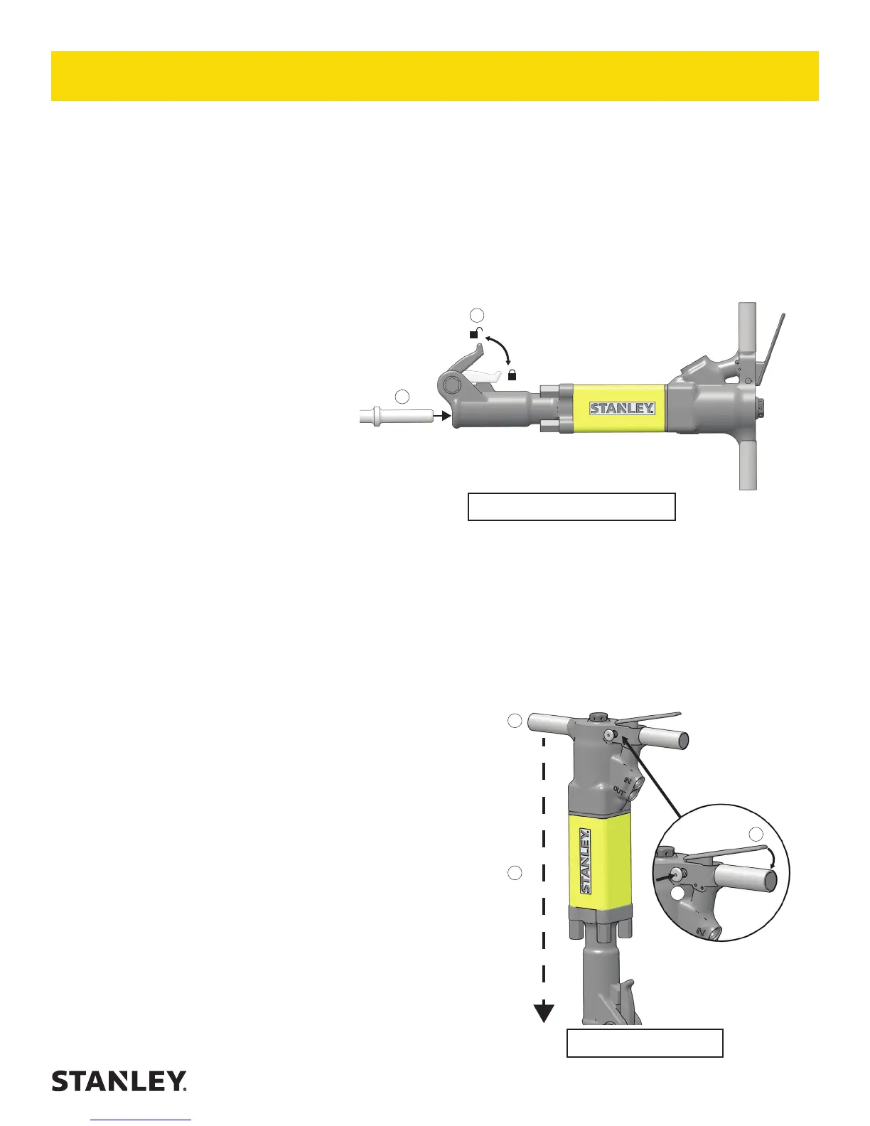
INSTALL TOOL BIT - FIG. 2
1. Rotate the latch on the breaker foot
downward (pointing away from the tool).
2. Insert the tool bit into the foot and pull
the latch up to lock the tool bit in place.
Note: Never use the tool if the bit is not
locked in the tool retainer.
Note: Model BR8717201 takes 6-1/4 inch
tool bits. All other models take 6 inch
tool bits.
CONNECT HOSES
1. Wipe all hose couplers with a clean, lint-free cloth before making connections.
2. Connect the hoses from the hydraulic power source to the tool ttings or quick disconnects. It is a good practice
to connect return hoses rst and disconnect them last to minimize or avoid trapped pressure within the tool.
3. Observe ow indicators stamped on hose couplers to ensure that uid ow is in the proper direction. The female
coupler on the tool hose is the inlet coupler.
4. Move the hydraulic circuit control valve to the ON position to operate the tool.
Note: If uncoupled hoses are left in the sun, pressure increase within the hoses may make them dicult to
connect. When possible, connect the free ends of the hoses together.
OPERATION PROCEDURES - FIG. 3
1. Observe all safety precautions.
2. Install the appropriate tool bit for the job.
3. Wrap your hands around the handles and stand in back of the
tool, using your leg against the snap-on ller for tool stability.
Note: Hold the tool correctly and be ready to counteract normal
or sudden movements. Have both hands available.
4. Place the breaker bit on the material to be broken, at a 90°
angle. Apply down pressure.
5. Push in the trigger lock (CE models only).
6. Slowly squeeze the trigger to start breaking. Squeeze harder
for fast speed operation.
7. When starting, break until the tool bit breaks through, then repo-
sition the bit. Do not use the tool bit as a lever to move material.
Note: Never cool a hot tool bit in water. Tools can become
brittle and can fail.
OPERATION
Figure 2 - Installing the Bit
1
2
Figure 3 - Tool Use
3
4
5
6