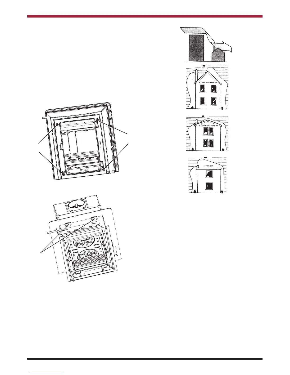
Then remove the 4 front fixing screws (see Fig.10)
which will allow the front casting and the surround-
ing shroud to be removed from the boiler by sliding
it to the left to clear the secondary air control rod and
then pulling it forward, in some circumstances it may
be necessary to unscrew the secondary air contol
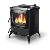
rod before removing the front. The wall flange can
then be removed by unscrewing the fixings on top
and sliding it up clear of the guides. (see Fig.11)
Make the required connections and replace the front
in reverse order making sure that the front seals fully
to the boiler.
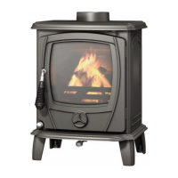
DOWN DRAUGHTS
However well designed constructed and positioned,
the satisfactory performance of the flue can be
adversely affected by down draught caused by near-
by hills, adjacent tall buildings or trees. These can
deflect wind to blow directly down the flue or create
a zone of low pressure over the terminal. A suitable
anti-down draught terminal or cowl will usually effec-
tively combat direct down blow but no cowl is likely
to prevent down draught due to a low pressure zone.
(See Fig.12)
Direction of wind
Direction of wind
Direction of wind
Pressure zone
Pressure zone
Suction zone
Suction zone
Pressure zone Suction zone
Fig 12
Fig 10
Front Fixing
Screws
Front Fixing
Screws
Top Fixings
Fig 11
7
VENTILATION AND COMBUSTION AIR
REQUIREMENTS
It is imperative that there is sufficient air supply to
support correct combustion. The minimum effective
air requirement for this appliance is 54cm
2
. When
calculating combustion air requirements for this
appliance use the following equation: 550mm
2
per
each kW of rated output above 5 kW should be pro-
vided, where a flue draught stabiliser is used the
total free area shall be increased by 300mm
2
for
each kW of rated output. If there is another appli-
ance using air fitted in the same or adjacent room, it
will be necessary to provide an additional air supply.
Especially Airtight Properties:-
If the stove is being fitted in a property where the
design air permeability is less than 5m
3
/ (h.m
2
) (nor-
mally newer properties built from 2006), then a per-
manent ventilation must be fitted to provide 550mm
2
of ventilation for each kW of rated output. If a
draught stabiliser is also fitted then the requirement
is 850mm
2
per kW of rated output.