15
G
B
safety.
● When fitting a tool, the flow of air in output must
beswitchedoff.
● When using compressed air, you must know and
comply with the safety precautions to be adopted
foreachtypeofapplication(inflation,pneumatic
tools, painting, washing with water-based
detergentsonly,etc.).
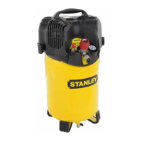
2. LAYOUT
1. Shroud
2. Pressurevessel
3. Wheel
4. Supportingfoot
5. Quick-lockcoupling(regulatedcompressedair)
6. Pressuregauge(forreadingthepreset
pressurebymeansofregulator)
7. Pressureregulator
8. ON/OFFswitch
9. Transportationhandle
10.Safetyvalve
11. Receivercondensationdrainagetap
12.Pressuregauge(forreadingthetankpressure)
13.Axle
14.Clip
15.Bolt
16.Nut
17.Washer
3. SCOPE OF USE
The compressor is designed for generating
compressed air for tools operated by compressed
air.
Please note that our equipment has not been
designed for use in commercial, trade or industrial
applications. Our warranty will be voided if the
machine is used in commercial, trade or industrial
businessesorforequivalentpurposes.
Themachineistobeusedonlyforits prescribed
purpose.Anyotheruseisdeemedtobeacaseof
misuse.Theuser/operatorandnotthemanufacturer
will be liable for any damage or injuries of any kind
causedasaresultofthis.
4. POINTS TO NOTE
WHEN SETTING UP THE
COMPRESSOR
● Examinethemachineforsignsoftransitdamage.
Report any damage immediately to the company
whichdeliveredthecompressor.
● The compressor should be set up near the
workingconsumer.
● Avoid long air lines and long supply lines
(extensions).
● Makesuretheintakeairisdryanddust-free.
● Do not set up the compressor in damp or wet
rooms.
● The compressor may only be used in suitable
rooms (with good ventilation and an ambient
temperature from +5°C to +40°C). There must
be no dust, acids, vapors, explosive gases or
inflammablegasesintheroom.
● Thecompressorisdesignedtobeusedindry
rooms. It is prohibited to use the compressor
in areas where work is conducted with sprayed
water.
5. ASSEMBLY AND STARTING
Warning!
You must fully assemble the appliance before
using it for the first time.
5.1 Fitting the wheels (Pic. 3 ÷ 4)
FitthesuppliedwheelsasshowninPic.3&4:
● Pic.3a&3b:Assemblyofwheelkit-versionA
Assembly by sequence: a, b, c, d, e
● Pic.4a&4b:Assemblyofwheelkit-versionB
5.2 Fitting the supporting foot (ref. 4)
FitthesuppliedrubberstopperasshowninPic.5.
5.3 Voltage
The compressor is equipped with a mains cable
withshock-proofplug.Thiscanbeconnectedtoany
230V~50Hzshock-proofsocketwhichisprotected
 Loading...