204038
Rev. C, 01/17/12
© 2012, THE STANLEY WORKS. ALL RIGHTS RESERVED. 4 of 19
2.2 Header Components
NOTE:
Table 2-2 shows the list of header components for both the DE-MC521 and MC521 Pro controllers.
Table 2-2. Header Components for DE-MC521 and MC521 Pro
Part Name
(EITHER) Terminal Block Assembly
(OR) PC Board I/O Assembly
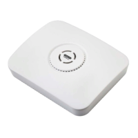
Buzzer and Bracket Assembly
4-Contact Plate Assembly
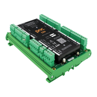
(EITHER) DE-MC521 Controller
(OR) MC521 Pro Controller; single or dual motor
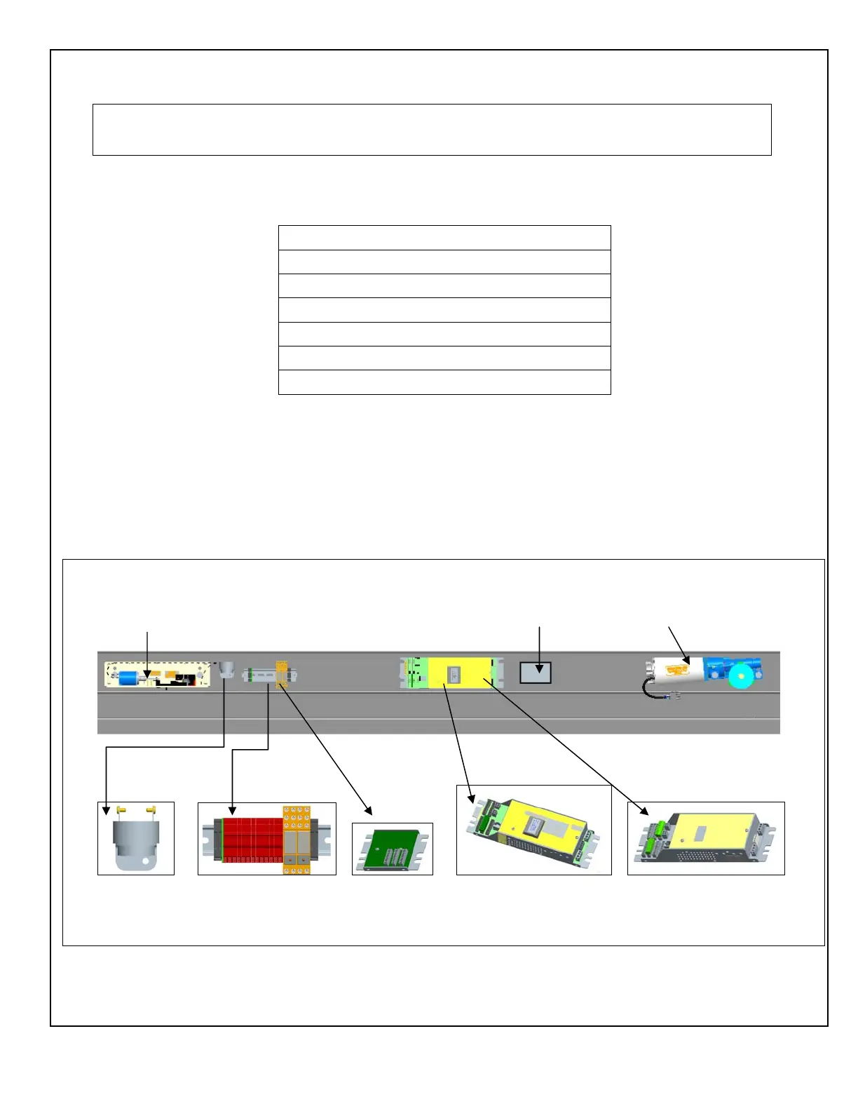
2.2.1 Figure 2 illustrates the (typical) components on the track inside the header:
a. DE-MC521 Controller OR MC521 Pro Controller
b. Terminal Block Assembly OR PC Board I/O Assembly
c. Buzzer and Bracket assembly
2.2.2 SECURE all wire harnesses with cable ties.
Figure 2. DE-MC521 AND MC521 Pro Typical Layout for Components in the Header
Solenoid Lock 24 VDC Power Supply Motor Gear Box
Buzzer Assy. Terminal Assy. OR PC Board DE-MC521 OR MC521 Pro
I/O Assembly