204038
Rev. C, 01/17/12
© 2012, THE STANLEY WORKS. ALL RIGHTS RESERVED. 6 of 19
2.4.2 CYCLE the door several times, and ENSURE the 4-contact switch block assemblies on
the hanger leading edges mate properly with the center contact plate as the doors come
together.
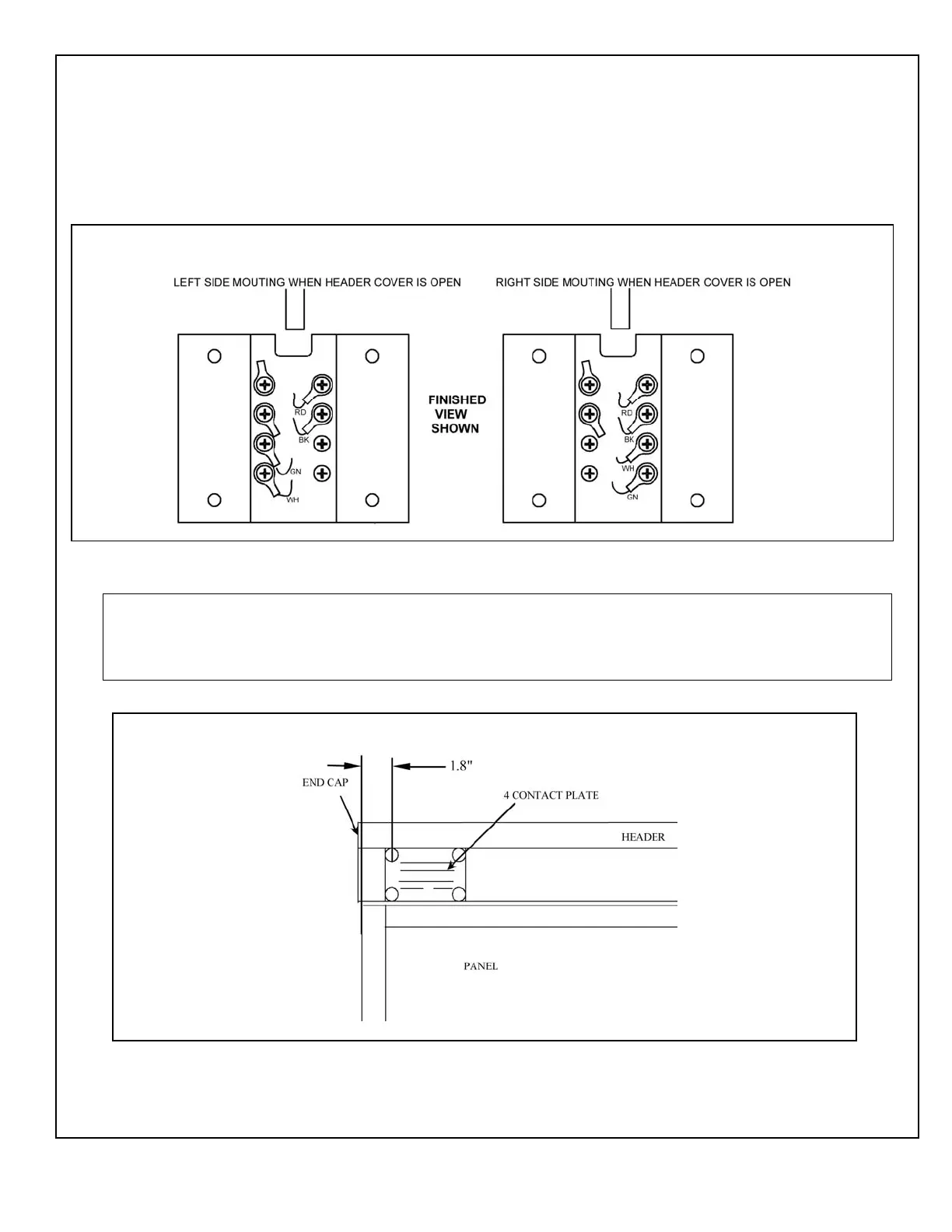
2.5 The 4-Contact Plate Assembly for Single-Slide Doors
2.5.1 Figure 4 illustrates the configuration for the left side or right side mounting.
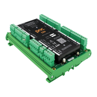
2.5.2 Figure 5 illustrates the 4-contact plate assembly installation for Single Side Doors.
NOTE:
The 4-contact plate must align properly with the four-contact switch block assembly on the hanger to
ensure the electrical connection to the door panel. The position of the four-contact switch block assembly
can be adjusted for vertical alignment.
Figure 4. Configuration for Left and Right Side 4-Contact Plate Assembly Mounting
Figure 5. The 4-Contact Plate Assembly for Single-Slide Doors (Left Side Mounting Shown)