EasyManua.ls Logo

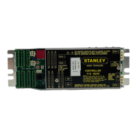
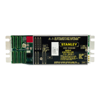
Stanley 204143 User Manual

Stanley 204143
48 pages
To Next Page IconTo Next Page
Page #1 background imageLoading...
Page #1 background image
Stanley Part Number 204143
REV 5 10/2019
Copyright 2019 Stanley Access Technologies, LLC.
Prohibition on Copying: Any unauthorized reproduction, disclosure or distribution of copies by any
person of any portion of this work may be a violation of copyright law of the United States of America
and other countries, could result in the awarding of statutory damages of up to $250,000 (17 USC 504)
for infringement, and may result in further civil and criminal penalties.
All rights reserved.
All manuals can be found at
www.stanleymobileapps.com
iQ Controller
Installation and Operation Manual
204143
FOR SWING AND FOLD DOORS

Questions and Answers:

Stanley 204143 Specifications

General IconGeneral
BrandStanley
Model204143
CategoryController
LanguageEnglish

Summary

General Description

Intended Use

Describes the manual's purpose and scope for the iQ controller.

Applicability

Specifies which iQ control boxes this manual covers for Magic-Swing/Force.

Precautions

Highlights safety and compliance requirements for door system installation.

Features and Functions

Lists the key capabilities and functions of the iQ controller.

Wiring Instructions

Evaluate Power Requirements

Details the necessary power source specifications for the door system.

Connecting Main Power Wiring

Instructions for safely connecting the main power supply to the control box.

Connecting Breakout Status Signal Wiring (Magic-Swing Operators)

Wiring for breakout status signal on Magic-Swing operator.

Connecting Breakout Status Signal Wiring (Magic-Force Operators)

Wiring for breakout status signal on Magic-Force operator.

Wiring the Operator Switch Module (Magic-Force Operators)

Instructions for connecting the operator switch module to the controller.

Wiring the Operator for Required Handing (Magic-Force Operators)

Configures door handing for Magic-Force operators.

Wiring the Power Close Speed Module

Connects the Power Close Speed Module to the controller.

Wiring the "ON/OFF/HOLD OPEN” Switch and Power Switch

Connects operator function switches and the main power switch.

Wiring the Door Activation or Safety Device

Connects external activation devices or safety sensors.

Wiring Swing Guard T

Connects the Swing Guard T sensor system.

Wiring Bodyguard-T

Connects the Bodyguard-T system.

Wiring Superscan-T

Connects the Superscan-T sensor.

Wiring Holding Beam

Connects the holding beam sensor.

Wiring Other Sensors

General instructions for connecting various other sensors.

Tune-In Instructions

Tuning in the iQ Using the Controller Pushbuttons

Guides manual setup and tune-in using the controller's pushbuttons.

Status Codes and Door States

Normal Operation Status

Status code indicating normal system operation.

Obstruction Status

Status code for door obstruction detection.

Breakout Status

Status code for breakout condition.

System Error Codes

Codes indicating general system errors.

Communication Error Codes

Codes for internal communication failures.

Motor Drive Error Codes

Codes for motor drive failures.

Stall State Codes

Codes indicating the door is in a stall.

Configuration Status Codes

Codes for unconfigured or FIS states.

Encoder Related Error Codes

Codes for encoder issues.

Learn Error Codes

Codes for errors during the learning process.

Troubleshooting Mode Status

Status indicating troubleshooting mode.

Door Held Open Status

Status code for door held open.

Door Length Error Status

Error code for incorrect door length.

Motor Drive Error Status

Error code for motor drive issues.

Power Close Control Failure Status

Failure in power close control.

Sensor Failure Status Codes

Codes for various sensor failures.

Fire Alarm Active Status

Status code for fire alarm activation.

Closed Door State

Indicates the door is fully closed.

Opening Door State

Indicates the door is in the process of opening.

Open Check Door State

Door is in the open check phase.

Full Open Door State

Indicates the door is fully open.

Close Check Door State

Door is in the close check phase.

Open Stop Door State

Door has stopped in the open position.

Close Stop Door State

Door has stopped in the closed position.

Power Close Door State

Door is operating in power close mode.

Lock Release Door State

Door is in the lock release phase.

Power Assist Door State

Door is operating in power assist mode.

Power Close at Closed Door State

Door is in power close at closed state.

Final Tune-In Adjustments

Adjust Close Check Cam

Adjusts the close check cam for proper operation.

Adjust Open Speed

Sets the door's opening speed.

Adjust Open Check Speed

Sets the speed during the open check phase.

Adjust Close Speed Rheostat

Adjusts the close speed using a rheostat.

Adjust Stall Torque

Sets the stall torque for the motor.

Adjust Torque

Adjusts the motor torque.

Adjust Time Delay

Sets the time delay for door operations.

Adjust Magic-Touch™ Hold Open Time

Sets hold open time for Magic-Touch activation.

Adjust Breakout and Breakout Status Cams

Adjusts breakout cams for proper function.

Adjust Power Close Speeds, Torques and Angles

Fine-tunes power close parameters.

Ensure ANSI/BHMA, and UL Compliance

Verifies compliance with ANSI/BHMA and UL standards.

Verify Safety Logic and JP301 Installation

Checks safety logic selection and JP301 installation.

Attachments

Attachment 1: Breakout Status Wiring for Magic-Swing Operators

Wiring diagram for breakout status on Magic-Swing operators.

Attachment 2: Magic-Force Wiring Diagram—iQ

Wiring diagram for Magic-Force operators.

Attachment 3: Magic-Swing Wiring Diagram—iQ

Wiring diagram for Magic-Swing operators.

Attachment 4: Monitored Sensors Wiring Diagrams (Sheet 1 of 14)

Wiring for monitored Door Mounted Stall & ACT sensors.

Attachment 4: Monitored Sensors Wiring Diagrams (Sheet 2 of 14)

Wiring for monitored pair Door Mounted Stall & ACT sensors.

Attachment 4: Monitored Sensors Wiring Diagrams (Sheet 4 of 14)

Wiring for Overhead Presence & Photobeam sensors.

Attachment 4: Monitored Sensors Wiring Diagrams (Sheet 7 of 14)

Wiring for Overhead Presence Folding Door sensors.

Attachment 4: Monitored Sensors Wiring Diagrams (Sheet 8 of 14)

Wiring for Door Mounted Stall & ACT sensors.

Attachment 4: Monitored Sensors Wiring Diagrams (Sheet 9 of 14)

Wiring for pair Door Mounted Stall & ACT sensors.

Attachment 4: Monitored Sensors Wiring Diagrams (Sheet 10 of 14)

Wiring for two Overhead Presence Folding Doors.

Attachment 4: Monitored Sensors Wiring Diagrams (Sheet 12 of 14)

Wiring for Door Mounted Stall with Overhead Presence.

Attachment 4: Monitored Sensors Wiring Diagrams (Sheet 13 of 14)

Wiring for pair Door Mounted Stall with Overhead Presence.

Attachment 4: Monitored Sensors Wiring Diagrams (Sheet 14 of 14)

Wiring for Door Mounted Stall with two Overhead Presence.

Attachment 5: Non-Monitored Sensors Wiring Diagrams (Sheet 1 of 3)

Wiring for non-monitored Door Mounted Stall & ACT sensors.

Attachment 5: Non-Monitored Sensors Wiring Diagrams (Sheet 2 of 3)

Wiring for non-monitored pair Door Mounted Stall & ACT sensors.

Attachment 5: Non-Monitored Sensors Wiring Diagrams (Sheet 3 of 3)

Wiring for non-monitored Dual Egress sensors.

Attachment 6: iQ Terminal Block Connections—TB1 through TB7

Details terminal block assignments for the iQ controller.

Attachment 7: iQ Controls and Indicators (Sheet 1 of 2)

Identifies controls and indicators on the iQ controller.

Attachment 7: iQ Controls and Indicators (Sheet 2 of 2)

Lists and describes the iQ controller's components.

Attachment 9: Hand Held Device Troubleshooting Aid—Swing/Fold (Sheet 1 of 1)

Provides a troubleshooting aid for Swing/Fold doors using a handheld device.

Attachment 10: Recommended Values for Door Configurations (Sheet 1 of 1)

Provides recommended settings for various door configurations.

Attachment 11: iQ Controller Fine Tuning (Sheet 1 of 1)

Offers guidance for fine-tuning iQ controller settings.

Related product manuals