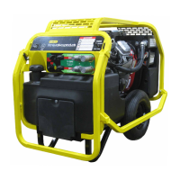
12 ► HP210 User Manual
ENGINE MAINTENANCE SCHEDULE
Follow the maintenance instructions provided in the engine
“Operating & Maintenance Instructions” manual.
HYDRAULIC SYSTEM MAINTENANCE
• Check hydraulic uid level daily and ll if needed.
• Check hydraulic lines and ttings daily for leaks, kinks
or damage. Do not use your hand to perform this
check.
• Remove condensed moisture from the hydraulic uid.
1. Set the ow selector to a 5 GPM/20 LPM circuit
ow.
2. Start the engine and pump the uid, out of the
pressure port, into a 5 gal. container.
3. When hydraulic tank is empty, turn the Ignition
Switch to the “Off” position.
4. Let the water settle to the bottom of the
container.
5. Pour the hydraulic uid back into the tank, being
careful to not disturb the water sitting at the
bottom of the container.
• Change the hydraulic lter every 200 hours of
operation. Change more often if used in cold, moist or
dusty conditions.
• Check oil cooler. Remove debris with air pressure.
BATTERY
• Do not charge the battery with an automotive battery
charger. Charging at higher than 2 amps will damage
the battery.
• If the engine stalls during operation, set the Ignition
Switch to the “OFF” position to preserve battery charge.
STORAGE
• Clean the unit thoroughly. Do not pressure wash.
• Always store the unit in a clean and dry location.
• If storing for over 30 days, add an additive to the fuel
tank to prevent the fuel from gumming. Run the engine
to circulate the additive.
• Replace the crankcase oil.
GENERAL
Tests should be performed periodically to ensure HP210 is
operating at maximum efciency. STANLEY Circuit Tester
(part number 04182) can be used to isolate problems in
both the engine and hydraulic system.
TESTING THE HYDRAULIC CIRCUIT
Test to ensure the hydraulic pump is supplying the correct
ow and pressure, and that the system relief valve is
operating properly. Before testing, make sure the engine is
warm and operating smoothly.
1. Turn the Flow Switch to the “FLOW OFF” position.
2. Set the Flow Selector Knob to the ow you would like
to test.
3. Connect the STANLEY Circuit Tester to the tool hoses.
4. Fully open the tester restrictor valve (counterclockwise).
5. Start the engine.
6. The test ow gauge should read +/- 1 GPM of the
selected ow.
7. Slowly turn the restrictor valve clockwise while
watching the pressure gauge. The ow rate should not
change as the pressure reaches 2100-2200 psi/148-
155 bar.
8. At 2100-2200 psi/148-155 bar, the relief valve should
begin to open. The ow rate should start to drop
because the relief valve is allowing uid to bypass to
the hydraulic uid tank. The relief valve is preset at the
factory. If it does not open within the above range, the
relief valve must be reset as follows:
a. The relief valve is located on the right side of the
unit, behind the dash panel (10, page 16). Use a
wrench to loosen the nut on the relief valve.
b. Use an Allen wrench to adjust the relief valve.
Turn clockwise to raise the opening pressure, and
counterclockwise to reduce the opening pressure.
c. Tighten the nut and repeat the test.
MAINTENANCE & TESTING