7
12 VOLT DC CHARGING METHOD
Charging the unit from an external 12 volt DC power source requires the use of the optional 12
Volt DC adapter (not included).
1. Lift the protective cover of the Built-in 120 V AC Charger located on the back of the unit. Make
sure the AC extension cord is disconnected from the 120 V AC Charger.
2. Insert the barrel tip of the 12 V DC Charging Adaptor into the 12 V DC Charging Port on the
back of the unit.
3. Insert the grooved tip of the 12 V DC Charging Adaptor into the vehicle’s 12 V DC accessory
outlet or other functioning 12 V DC power source. The 12V DC Charging Adapter LED Indicator
will light to indicate the unit is properly plugged into the 12V DC power source and is in
charging.
4. Charge the unit until the Battery Status Icon shows 4 solid bars when either the Area Light,
USB or Compressor Power Button is pressed (with the adapter unplugged from the unit).
5. When charging is complete, remove the DC Charging Adaptor from the unit and the 12 V DC
power source when not in use and store in a safe place.
Notes: Some vehicles require that the ignition be switched to the accessory outlet position in order to power
the accessory outlet. Do not leave the unit unattended when charging using the this method.
JUMP-STARTER
This Portable Power Station/Jump-Starter is equipped with an On/Off Power Switch. Once the
connections are properly made, turn the switch on to jump-start the vehicle.
IMPORTANT: Make sure the Compressor Power Button has been turned off before attempting to
use the unit as a Jump Starter.
1. Turn off vehicle ignition and all accessories (radio, A/C, lights, connected cell phone chargers,
etc.). Place vehicle in “park” and set the emergency brake.
2. Make sure the Jump-Starter Power Switch is turned to off.
3. Remove jumper clamps from clamp tabs. Connect the red clamp first, then the black clamp.
4. Procedure for jump-starting a NEGATIVE GROUNDED SYSTEM (negative battery
terminal is connected to chassis) (MOST COMMON)
4a. Connect positive (+) red clamp to vehicle battery’s positive terminal.
4b. Connect negative (–) black clamp to chassis or a solid, non-moving, metal vehicle
component or body part. Never clamp directly to negative battery terminal or moving part.
Refer to the automobile owner’s manual.
5. Procedure for jump-starting POSITIVE GROUND SYSTEMS
Note: In the rare event that the vehicle to be started has a Positive Grounded System (positive battery
terminal is connected to chassis), replace steps 4a and 4b above with steps 5a and 5b, then
proceed to step 6.
5a. Connect negative (–) black clamp to vehicle battery’s negative terminal.
5b. Connect positive (+) red clamp to vehicle chassis or a solid, non-moving, metal vehicle
component or body part. Never clamp directly to positive battery terminal or moving part.
Refer to the automobile owner’s manual.
6. When clamps are connected properly, turn the Jump-Starter Power Switch to ON. The backlit
LCD screen will display the following:
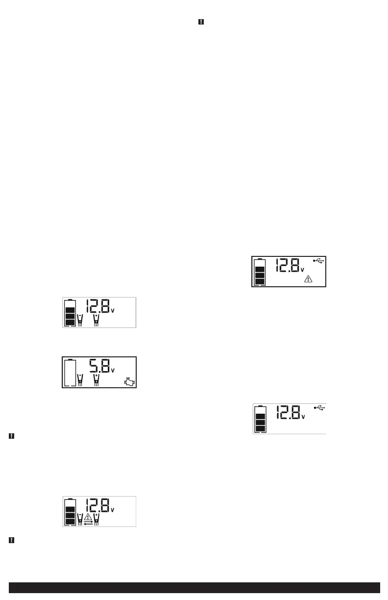
The Battery Status icon, Battery Voltage Indicator, Clamp Icons and the “+” and”–” signs light
solid. The jump starter icon will flash to indicate the clamps are properly connected.
7. Turn ON the ignition and crank the engine in 5-6 second bursts until engine starts. The backlit
LCD screen will display the following:
The Battery Status Icon, the Battery Voltage Indicator, Jump Starter Icon, Clamp Icons and the
“+” and”–” signs light solid to indicate the unit is jump-starting.
8. Turn the Jump-Starter Power Switch back to the off position.
9. Disconnect the negative (–) engine or chassis clamp first, then disconnect the positive (+)
battery clamp.
IMPORTANT: Always turn the unit off when not in use. Recharge this unit fully after each use.
WARNING – TO REDUCE THE RISK OF SERIOUS INJURY OR PROPERTY DAMAGE:
• Follow all safety instructions found in the “Specific Safety Instructions for Jump Starters” section
of this instruction manual.
• Never touch red and black clamps together. This can cause dangerous sparks, power arcing, and/
or explosion.
• If the clamps are connected incorrectly with regard to polarity, the unit will sound a continuous
alarm until the clamps are disconnected. The backlit LCD Screen will display the Battery Status
Icon, the Battery Voltage Indicator and the Clamp Icons. The “+” and”–” signs above the Clamp
Icons, the Arrow Icons and the Alarm Icon will flash. The backlit LCD screen will display the
following:
CAUTION – This unit will suffer permanent damage if the Jump Starter Power Switch
is turned on while the clamps are connected with reverse polarity. Disconnect the clamps and
reconnect to battery with correct polarity before operating the unit.
• Always disconnect the negative (black) jumper cable first, followed by the positive (red) jumper
cable, except for positive grounded systems.
CAUTION – TO REDUCE THE RISK OF PROPERTY DAMAGE:
• Vehicles that have on-board computerized systems may be damaged if vehicle battery is jump-
started. Before jump-starting this type of vehicle, read the vehicle manual to confirm that
external-starting assistance is advised.
• Excessive engine cranking can damage the vehicle‘s starter motor. If the engine fails to start after
the recommended number of attempts, discontinue jump-start procedure and look for other
problems that need to be corrected.
• If vehicle fails to start, turn off the ignition, turn off the Jump-Starter Power Button, disconnect
the jump-start system’s leads and contact a qualified technician to investigate why the engine
did not start.
AREA LIGHT
The area light is controlled by the Area Light Power Button on the Control Panel (refer to the
“Features” section to locate).
1. Press the Area Light Power Button once to turn the light on.
2. Press the Area Light Power Button again to turn the area light off.
When the Area Light Power Button is pressed to turn it on, a beep will sound. The backlit LCD
screen will turn on for 10 seconds (only) and will then continuously display the Battery Status Icon
and the Battery Voltage Indicator.
Periodically check the unit’s battery status on the backlit LCD screen. Four solid bars in the battery
icon indicates a full battery. When the battery level is nearly empty with only one solid bar or
completely empty with four empty bars, the unit must be recharged at this time or the unit’s built-
in low voltage protection will activate. The empty Battery Status Icon will flash for a short period of
time before automatic shut down.
IMPORTANT: Make sure the Area Light is turned off when the unit is being recharged or stored.
USB PORTS
The USB power button and the three USB ports are located on the front of the unit (see the
“Features” section to locate).
IMPORTANT NOTES:
1. The three USB ports provide 3.1A (5V) each.
2. When the USB Ports are in use, the unit will monitor for the following USB fault conditions on
all the USB Ports: low battery voltage fault, overload and short circuit. In any of these cases, the
backlit LCD screen will continuously display the following:
The Fault Icon will flash. The USB Ports will automatically shut down. Should this occur:
2a. Disconnect the USB-powered device and press the USB Power Button again to turn off the
USB Ports immediately.
2b. Make sure the unit does not need to be recharged.
2c. Allow the unit to cool down for several minutes before attempting to use the USB Ports
again.
2d. If a fault occurs again, make sure that the total draw of the USB device plugged into the
USB Port does not exceed 3.1A (5V).
2e. If an individual USB device is within specifications and the fault occurs, have the USB device
checked for malfunction and do not continue to use it with these USB Ports.
3. This unit’s USB Ports do not support data communication. They only provide power to external
USB-powered devices. The USB Ports provide 3.1 A (5 V) each.
4. Some household USB-powered electronics will not operate with this unit.
Using the USB Ports
1. Press the USB Power Button to turn on all of the USB Ports. A beep will sound. The backlight
will turn on for 10 seconds (only). The backlit LCD screen will continuously display the
following:
The Battery Status Icon and Battery Voltage Indicator will light solid, as well as the USB Icon,
indicating the USB ports are ready to use.
2. Plug the USB-powered device into the USB power port(s) and operate normally.
3. Press the USB Power Button again to turn off the USB Ports.
Periodically check the unit’s battery status on the backlit LCD screen. Four solid bars in the battery
icon indicates a full battery. When the battery level is nearly empty with only one solid bar or
completely empty with 4 empty bars, the unit must be recharged at this time or the unit’s built-in
low voltage protection will activate. The empty Battery Status Icon will flash for a short period of
time before automatic shut down.
IMPORTANT: Make sure the USB Ports are turned off when the unit is being recharged or stored.
PORTABLE COMPRESSOR
The built-in 12 volt DC compressor is the ultimate compressor for all vehicle tires, trailer tires and
recreational inflatables. A nozzle adaptor is supplied that screws onto the end of the Sure Fit®
nozzle at the free end of the compressor hose. The compressor hose with tire fitting is stored in
the compressor hose storage compartment. Refer to the “Features” illustration for locations of
compressor hose. The Compressor Power Button and Increase (+) and Decrease (–) Compressor
Pressure Control Buttons are located on the control panel on the front of the unit.
Before proceeding, check the unit’s battery status on the LCD screen. Four solid bars in the battery
icon indicates a full battery. When the battery level is nearly empty with only one solid bar, the unit
 Loading...