204038
Rev. C, 01/17/12
© 2012, THE STANLEY WORKS. ALL RIGHTS RESERVED. 5 of 19
2.3 Installing the Components on the Header Cover or Jamb (if necessary)
2.3.1 INSTALL power key switch assembly as follows:
If installation is a Dura-Glide 3000, Refer to 203926, “Rotary/Key Switch
Instruction Manual,” for machining template and MOUNT power key switch
assembly to header cover.
If installation is a Dura-Glide 2000, Refer to 203926,“Rotary/Key Switch
Instruction Manual,” for machining template and MOUNT power key switch
assembly to header or jamb inside of building.
2.3.2 INSTALL rotary key switch assembly as follows:
If installation is a Dura-Glide 3000, Refer to 203926, “Rotary/Key Switch
Instruction Manual,” for machining template and MOUNT rotary function key
switch assembly to header cover.
If installation is a Dura-Glide 2000, Refer to 203926,“Rotary/Key Switch
Instruction Manual,” for machining template and MOUNT rotary key switch
assembly to header or jamb inside of building.
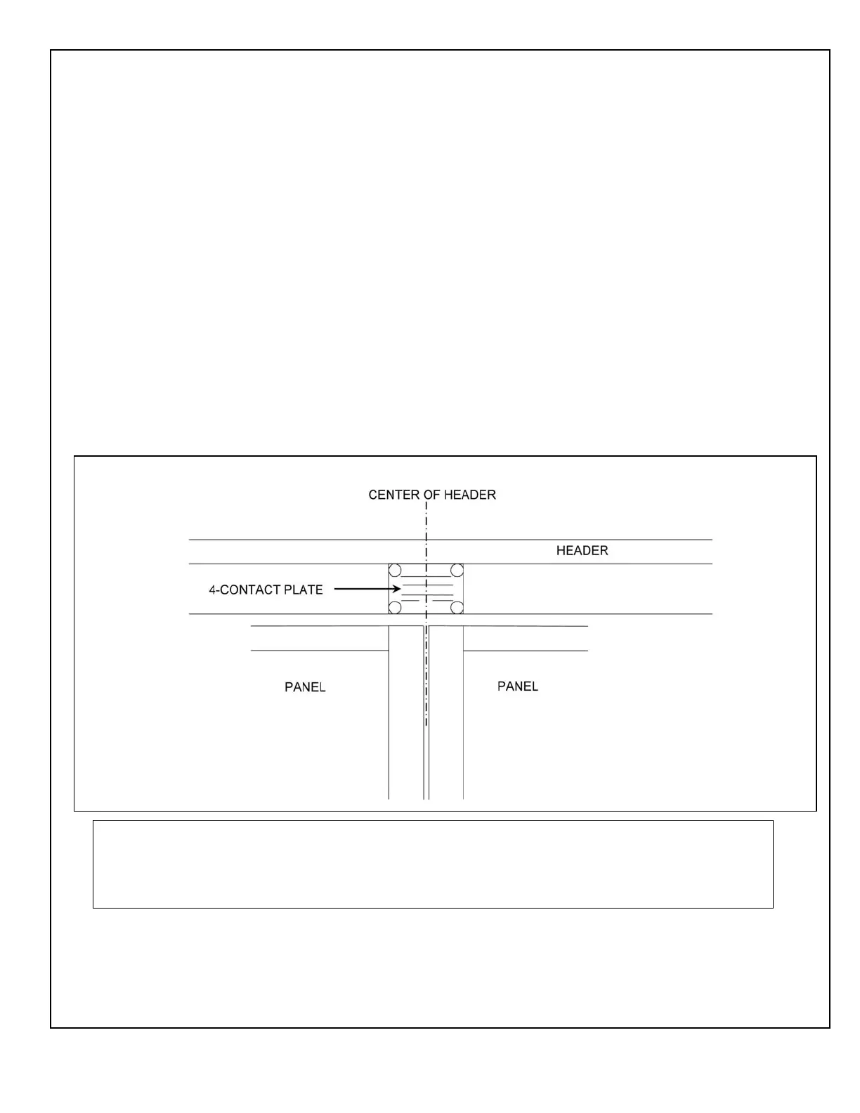
2.4 The 4-Contact Plate Assembly for Bi-parting Doors
2.4.1 Figure 3 illustrates the 4-contact plate assembly for Bi-parting Doors
NOTE:
The 4-contact plate assembly must align properly with the two 4-contact switch block assemblies on the
hangers to ensure the transfer of electrical connections to the door panels. The position of the four-contact
switch block assemblies can be adjusted for vertical alignment.
Figure 3. The 4-Contact Plate Assembly for Bi-parting Doors

 Loading...