204038
Rev. C, 01/17/12
© 2012, THE STANLEY WORKS. ALL RIGHTS RESERVED. 8 of 19
NOTE:
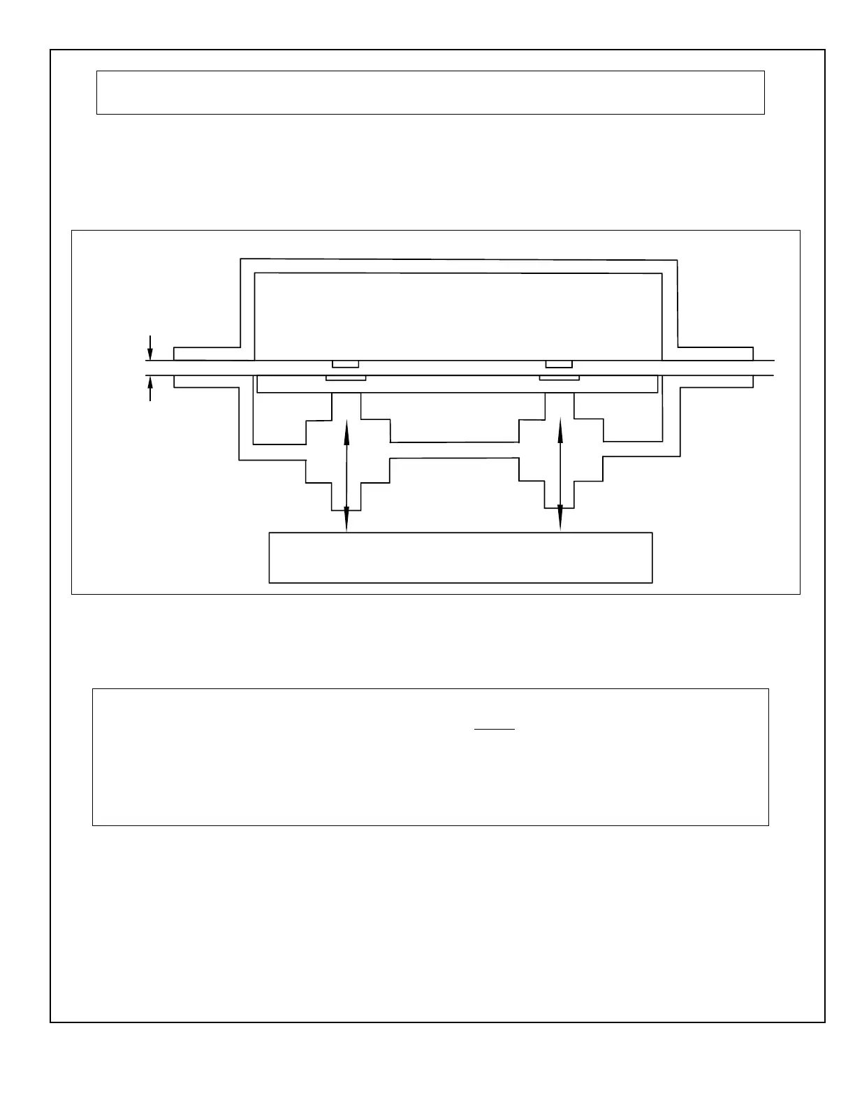
The typical gap required between the magnet and the armature is 0.120″.
2.8.4 If shear locks do not engage, refer to Figure 6 and, using the key wrench supplied with
the lock kit, ADJUST the shear lock assembly. After adjusting the armature, remove the
armature and tighten nuts at the bottom. Reassemble.
2.8.5 If necessary, ADJUST the 4-contact switch block assemblies and ENSURE proper
alignment with the center contact plate.
2.9 Troubleshooting the Delayed Egress System
2.9.1 Refer to Table 2-3 for a listing of symptoms and remedies.
NOTE
The following two conditions describe proper system operation:
1. Door is in CLOSED/LOCKED. The buzzer is OFF. The shear locks are energized. K1 LED is OFF. K2
LED is ON.
2. Door is in AUTOMATIC. The buzzer is OFF. The shear locks are de-energized. K1 LED is ON. K2
LED is OFF.
Figure 6. Adjusting the Shear Lock Assembly
ARMATURE
MAGNET
MIN. GAP
USE SUPPLIED KEY WRENCH TO ADJUST ARMATURE PLATE
TO APPROXIMATELY 0.080" to 0.120" OF GAP BETWEEN MAGNET
SURFACE.
DE003

 Loading...