02140-11-E Copyright
©
Stanley Security, Inc. 2014
2/9
Installation Instructions:
Wiring methods shall be in accordance with the National Electrical Code/NFPA 70/NFPA 72/ANSI, The Canadian Electrical Code, Part 1 and with all
local codes and authorities having jurisdiction. The product must be located indoors within the protected premises.
1. Mount unit in the desired location. Mark and predrill holes in the wall to line up with the top two keyholes in the enclosure. Install two
upper fasteners and screws in the wall with the screw heads protruding. Place the enclosure’s upper keyholes over the two upper screws,
level and secure. Mark the position of the lower two holes. Remove the enclosure. Drill the lower holes and install the two fasteners. Place
the enclosure’s upper keyholes over the two upper screws. Install the two lower screws and make sure to tighten all screws (Enclosure
Dimensions, pg. 8).
2. Secure enclosure to earth ground.
3. Set the DC output voltage to 24DC by setting SW1 to the open position on the power supply board (Figure 2-1a).
4. Connect unswitched AC power (120VAC 60Hz) to terminals marked [L, N] (Figure 1). Use 18 AWG for all power connections and 18 AWG
to 22 AWG for power limited circuits (AC Fail/Low Battery reporting). Secure green wire lead to earth ground. Keep power-limited wiring
separate from non power-limited wiring (120VAC 60Hz Input, Battery Wires). Minimum 0.25” spacing must be provided.
5. Measure output voltage before connecting devices. This helps avoid potential damage.
6. Connect the delayed egress exit device locking hardware positive leads to terminals marked 1 through 4 POS (+) on the PD8ULCB board
and negative leads to the NEG 1 terminals through 4 terminals.
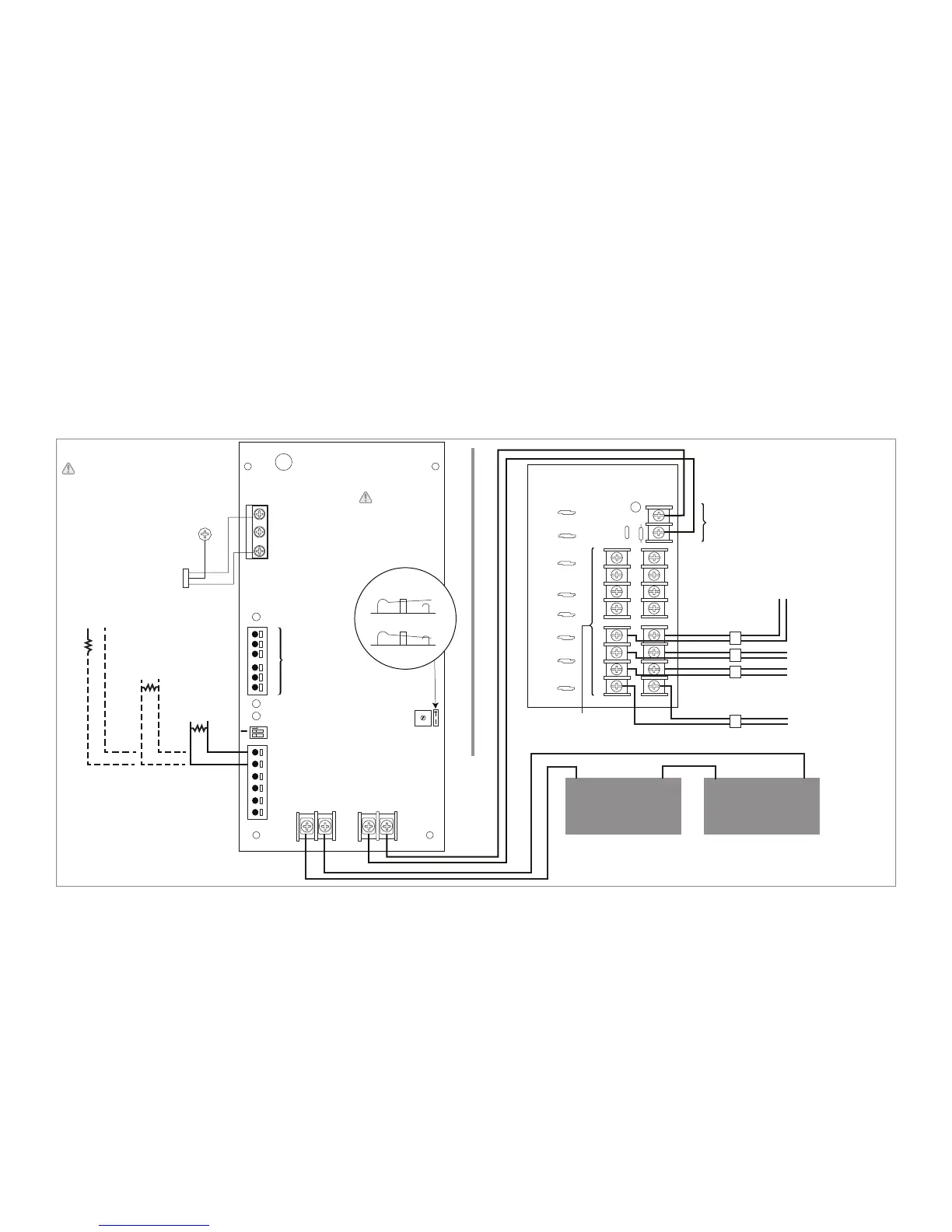
Figure 1 - Wiring Diagram for Connecting DE Exit Devices to a PS161-6 Power Supply
Note A 10k EOL (End of Line) Resistor must be installed across terminals marked (Trigger EOL Supervised) on the PS161-6 board or the
unit will remain in fire alarm condition.
7. For Access Control applications batteries are optional. When batteries are not used, a loss of AC will result in the loss of output voltage.
Batteries must be lead acid or gel type if used. Use two 12VDC batteries connected in series for 24VDC operation (Battery leads included).
8. Connect battery to terminals marked [-- BAT + ] (Figure 2 - 1g). Use two (2) 12VDC batteries connected in series for 24VDC operation
(battery leads included). Use batteries - Casil CL1270 (12V/7AH), CL12120 (12V/12AH), CL12400 (12V/40AH), CL12650 (12V/65AH)
batteries or UL recognized BAZR2 batteries of an appropriate rating.
9. To trigger the power supply from a re alarm control panel (FACP), connect signaling circuit of FACP to terminals marked Trigger End of
Line Supervised.
10. To delay AC reporting for 2 hrs. set dip switch [AC Delay] to OFF position (Figure 2 - 1c).
11. To delay AC reporting for 1 min. set dip switch [AC Delay] to ON position (Figure 2 - 1c).
Note Must be set to ON position for Burglar Alarm Applications.
Delayed Egress
Exit Device #1
Delayed Egress
Exit Device #2
Delayed Egress
Exit Device #3
Delayed Egress
Exit Device #4
L
G
N
NC
C
NO
NC
C
NO
BAT
FAIL AC FAIL
--- DC +
AC
DC
--- BAT +
– AUX + TRIGGER EOL
SUPERVISED
5A 250V
RESET
GND NO
Disable
Enable
2 hr.
1 min.
AC DELAY
SHUTDOWN
O
N
N
C O M M ON POWER OU TPUTS
P
FUSED POWER OUTPUTS
1 2 3 4 5 6 7 8
D1
INPUT
R1
LED
Divider
DC Output to Devices
(1P-8P Power Outputs)
(1N-8N Common Outputs)
AC1
Battery & AC
Supervision Circuit
(Power-limited)
Potentiometer
Power-limited
Green Lead
(Ground)
120VAC Power Mains
(Non Power-limited)
From Power Supply Board
(Factory Installed)
Open - 24V
Closed - 12V
Switch Detail
Closed - 12V
Open - 24V
Battery
Connections
(Non
Power-limited)
12VDC Rechargeable
Battery
+–
12VDC Rechargeable
Battery
+–
No Fire
Connections
N.O. Input
from
Fire Panel
N.C. Input
from
Fire Panel
OR OR
10K EOL
10K EOL
10K EOL
Separation of power-
limited wiring from
non power-limited
wiring must be at
least 1/4 inch.
Power must be
turned off
before changing
the voltage
select switch.
 Loading...