ENGLISH • 15
f Injuries caused by prolonged use of a tool. When
using any tool for prolonged periods ensure you take
regular breaks.
f Impairment of hearing.
f Health hazards caused by breathing dust developed
when using your tool (example:- working with wood,
especially oak, beech and MDF.)
USING AN EXTENSION CABLE
If an extension cable is requred, use an approved extension
cable suitable for the power input of this tool (see technical
data). The minimum conductor size is 1.5 mm
2
.
When using a cable reel, always unwind the cable
completely. Also refer to the table below:
Minimum gage for cord sets
Volts Total length of cord in meters
120V 0 - 7 7 - 15 15 - 30 30 - 50
220V 0 - 15 15 - 30 30 - 60 60 - 100
Rated
Ampere
range
Minimal cross-sectional area
of the cord in meters (mm
2
)
0 - 6 A 1.0 1.5 1.5 2.5
6 - 10 A 1.0 1.5 2.5 4.0
10 - 12 A 1.5 1.5 2.5 4.0
12 - 16 A 2.5 4.0 Not recommended
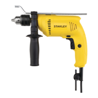
FEATURES (Fig. A)
1. Variable speed switch
2. Lock-on button
3. Forward/reverse slider
4. Drilling mode selector
5. Chuck
6. Depth stop
7. Side handle
ASSEMBLY
Warning! Before assembly, make sure that the tool
is switched off and unplugged.
Fitting the side handle and depth stop (Fig. A and B)
f Turn the grip counter clockwise until you can slide
the side handle (7) onto the front of the tool as shown
(Fig. A).
f Rotate the side handle into the desired position.
f Insert the depth stop (6) into the mounting hole
as shown (Fig. A).
f Set the drilling depth as described below.
f Tighten the side handle by turning the grip clockwise.
Fitting a drill bit (Fig. C)
f Open the chuck by turning the sleeve (5) counter clockwise.
f Insert the bit shaft (9) into the chuck (drill bit not included).
f Insert the chuck key (10) into each hole (8) in the side
of the chuck and turn clockwise until it is tight.
Removing and refitting the chuck (Fig.D)
f Open the chuck as far as possible.
f Remove the chuck retaining screw, located in
the chuck, by turning it clockwise using a screwdriver.
f Tighten an Allen key into the chuck and strike it with
a hammer as shown.
f Remove the Allen key. Remove the chuck
by turning it counter clockwise.
f To refit the chuck, screw it onto the spindle
and secure it with the chuck retaining screw.
USE
Warning! Let the tool work at its own pace.
Do not overload.
Warning! Before drilling into walls, floors or ceilings,
check for the location of wiring and pipes.
Selecting the direction of rotation (Fig. E)
For drilling and for tightening screws, use forward (clockwise)
rotation For loosening screws or removing a jammed drill
bit, use reverse (counter clockwise) rotation.
f To select forward rotation, push the forward/reverse
button (3) to the left position.
f To select reverse rotation, push the forward/reverse
button (3) to the right.
Warning! Never change the direction of rotation while
the motor is running.
Selecting the drilling mode
f For drilling in masonry, set the drilling mode selector
(4) to the position.
f For drilling in other materials and for screwdriving,
set the drilling mode selector to the position.
Setting the drilling depth (Fig. B)
f Slacken the side handle (7) by turning the grip
counter clockwise.
f Set the depth stop (6) to the desired positon.
The maximum drilling depth is equal to the distance
between the tip of the drill bit and the front end
of the depth stop.
f Tighten the side handle by turning the grip clockwise.
Switching on and off
f To switch the tool on, press the variable speed switch (1).
f The tool speed depends on how far you press the switch.
f As a general rule, use low speeds for large diameter
drill bits and high speeds for smaller diameter drill bits.