8 ► SPL31 User Manual
HTMA / EHTMA REQUIREMENTS
TOOL TYPE
HTMA
HYDRAULIC SYSTEM REQUIREMENTS
TYPE I TYPE II TYPE RR TYPE III
Flow range
4-6 GPM
(15-23 LPM)
7-9 GPM
(26-34 LPM)
9-10.5 GPM
(34-40 LPM)
11-13 GPM
(42-49 LPM)
Nominal operating pressure
(At the power supply outlet)
1500 psi
(103 bar)
1500 psi
(103 bar)
1500 psi
(103 bar)
1500 psi
(103 bar)
System relief valve setting
(At the power supply outlet)
2100-2250 psi
(145-155 bar)
2100-2250 psi
(145-155 bar)
2200-2300 psi
(152-159 bar)
2100-2250 psi
(145-155 bar)
Maximum back pressure
(At tool end of the return hose)
250 psi
(17 bar)
250 psi
(17 bar)
250 psi
(17 bar)
250 psi
(17 bar)
Measured at a max uid viscosity of:
(At minimum operating temperature)
400 ssu*
(82 centistokes)
400 ssu*
(82 centistokes)
400 ssu*
(82 centistokes)
400 ssu*
(82 centistokes)
Temperature: Suffi cient heat rejection capacity to limit
maximum uid temperature to:
(At maximum expected ambient temperature)
140° F
(60° C)
140° F
(60° C)
140° F
(60° C)
140° F
(60° C)
Minimum cooling capacity at a temperature di erence of
between ambient and uid temps
3 hp
(2.24 kW)
40° F
(22° C)
5 hp
(3.73 kW)
40° F
(22° C)
6 hp
(5.22 kW)
40° F
(22° C)
7 hp
(4.47 kW)
40° F
(22° C)
Note: Do not operate the tool at oil temperatures above 140° F (60° C). Operation at higher temperatures can cause operator
discomfort at the tool.
Filter minimum full- ow ltration 25 microns 25 microns 25 microns 25 microns
Sized for ow of at least:
(For cold temp startup and maximum dirt-holding capacity)
30 GPM
(114 LPM)
30 GPM
(114 LPM)
30 GPM
(114 LPM)
30 GPM
(114 LPM)
Hydraulic uid, petroleum based (premium grade, anti-
wear, non-conductive) Viscosity (at minimum and maximum
operating temps)
100-400 ssu
(20-82
centistokes)
100-400 ssu
(20-82
centistokes)
100-400 ssu
(20-82
centistokes)
100-400 ssu
(20-82
centistokes)
Note: When choosing hydraulic uid, the expected oil temperature extremes that will be experienced in service determine the most
suitable temperature viscosity characteristics. Hydraulic uids with a viscosity index over 140 will meet the requirements over a wide
range of operating temperatures.
*SSU = Saybolt Seconds Universal
CLASSIFICATION
EHTMA
HYDRAULIC SYSTEM
REQUIREMENTS
Flow range
3.5-4.3 GPM
(13.5-16.5
LPM)
4.7-5.8 GPM
(18-22 LPM)
7.1-8.7 GPM
(27-33 LPM)
9.5-11.6 GPM
(36-44 LPM)
11.8-14.5 GPM
(45-55 LPM)
Nominal operating pressure
(At the power supply outlet)
1870 psi
(129 bar)
1500 psi
(103 bar)
1500 psi
(103 bar)
1500 psi
(103 bar)
1500 psi
(103 bar)
System relief valve setting
(At the power supply outlet)
2495 psi
(172 bar)
2000 psi
(138 bar)
2000 psi
(138 bar)
2000 psi
(138 bar)
2000 psi
(138 bar)
Note: These are general hydraulic system requirements. See tool speci cation page for tool speci c requirements.
Oil Flow Hose Lengths Inside Diameter
USE
(
Press/Return)
Min. Working Pressure
GPM LPM FEET METERS INCH MM PSI BAR
Certi ed Non-Conductive Hose - Fiber Braid - for Utility Bucket Trucks
4-9 15-34 up to 10 up to 3 3/8 10 Both 2250 155
Conductive Hose - Wire Braid or Fiber Braid -DO NOT USE NEAR ELECTRICAL CONDUCTORS
4-6 15-23 up to 25 up to 7.5 3/8 10 Both 2500 175
4-6 15-23 26-100 7.5-30 1/2 13 Both 2500 175
5-10.5 19-40 up to 50 up to 15 1/2 13 Both 2500 175
5-10.5 19-40 51-100 15-30 5/8 16 Both 2500 175
5-10.5 19-40 100-300 30-90
5/8 16 Pressure 2500 175
3/4 19 Return 2500 175
10-13 38-49 up to 50 up to 15 5/8 16 Both 2500 175
10-13 38-49 51-100 15-30
5/8 16 Pressure 2500 175
3/4 19 Return 2500 175
10-13 38-49 100-200 30-60
3/4 19 Pressure 2500 175
1 25.4 Return 2500 175
13-16 49-60 up to 25 up to 8
5/8 16 Pressure 2500 175
3/4 19 Return 2500 175
13-16 49-60 26-100 8-30
3/4 19 Pressure 2500 175
1 25.4 Return 2500 175
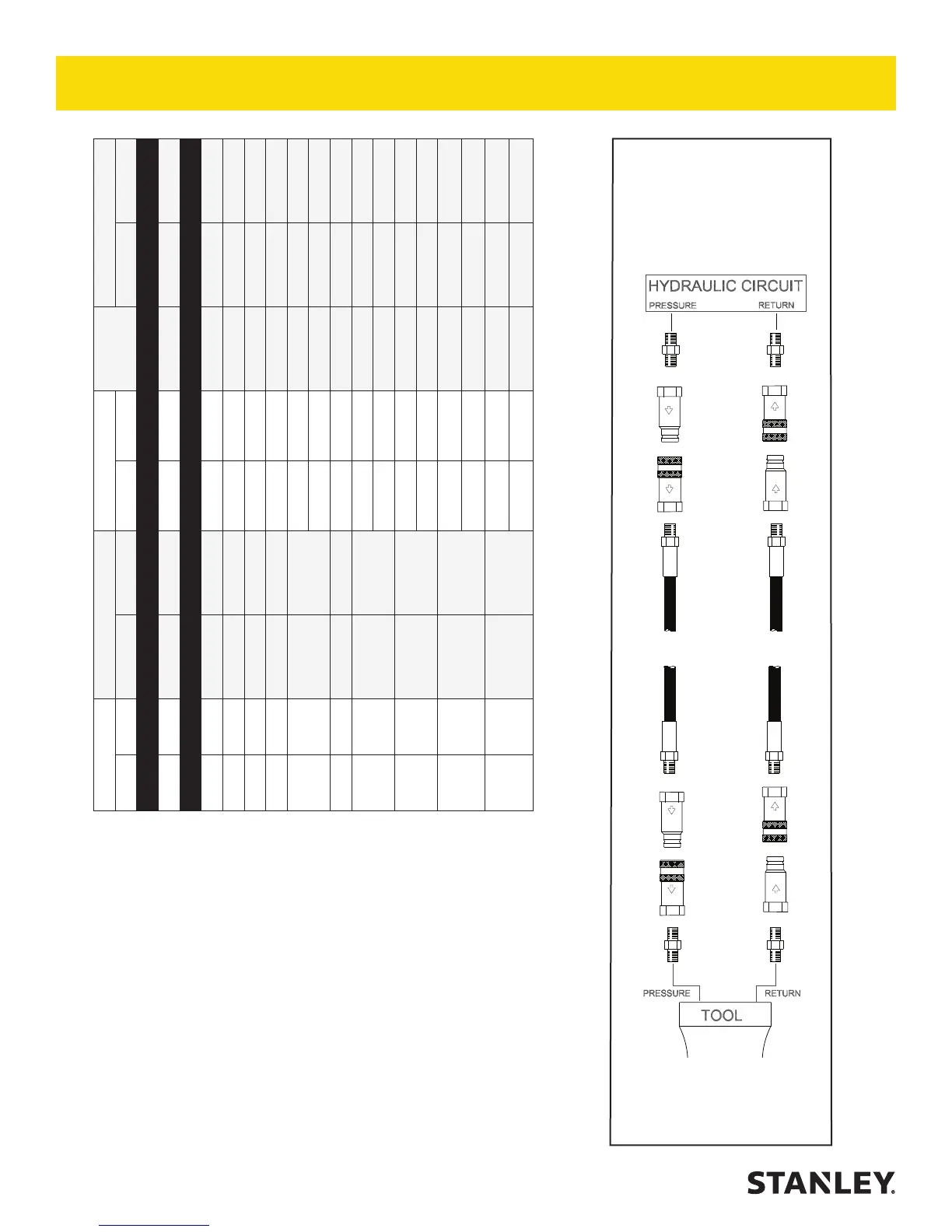
Figure 1. Typical Hose Connections
Tool to Hydraulic Circuit Hose
Recommendations
The chart to the right shows recommended
minimum hose diameters for various
hose lengths based on gallons per minute
(GPM)/liters per minute (LPM). These
recommendations are intended to keep return
line pressure (back pressure) to a minimum
acceptable level to ensure maximum tool
performance.
This chart is intended to be used for hydraulic
tool applications only based on STANLEY tool
operating requirements and should not be
used for any other applications.
All hydraulic hose must have at least a
rated minimum working pressure equal to
the maximum hydraulic system relief valve
setting.
All hydraulic hose must meet or exceed
speci cations as set forth by SAE J517.
HOSE RECOMMENDATIONS
 Loading...