DEUTSCH
1.
组装脚架
步骤
1
选择下列零件:
2
x
零件
1
1
x
零件
3
1
x
零件
5
如图
B1
,
B2
,和
B3
所示,将零件放在一起。 最佳和最简单的方法
是将零件松散地放在地板上。一旦确认所有零件均按照正确位置
摆放在一起,即可开始安装过程。
如图
B1
所示对齐孔并用螺栓固定。
此时请勿完全拧紧螺栓,螺母和垫圈。仅需通过手指拧紧即可。
步骤
2
重复步骤
1
,以便组装两个框架。
8
ENGLISH
uprights. Note that Part 2 should be positioned as shown in
Fig. B4. Connect Part 4 (top cross support) to the top of the
frame. Note that Part 4 should be positioned as shown in
Fig. B4.
Step 4
Now place and connect the ends of the top and center frame
supports to the frame. Take care to ensure that the supports
are positioned as shown in Fig. B5.
Step 5
Once you are satisfied that the frame is assembled correctly,
fully tighten ALL the bolts. Finally, assemble the 4 foot pads to
the bottom of each leg (see Fig. B6).
2. Assemble the stand’s legs
Step 1
Select the following parts:
2 x Part 1
1 x Part 3
1 x Part 5
Lay the parts together as shown in Fig. B1, B2, and B3. This
is best done by simply laying the parts loosely together on the
floor. Once you are satisfied that you have the parts correctly
laid together, start the fitting process.
Align the holes and secure with the bolts as shown in
Fig. B1.
DO NOT fully tighten the bolts, nuts and washers at this point.
Finger tight is sufficient.
Step 2
Repeat Step 1 so that there are two frames assembled.
Step 3
Select the following parts:
2 x Part 2
2 x Part 4
These will form the crosspieces between the previously
assembled frames. Lay the parts flat on the floor. Connect the
longer Part (2) and fix it to the frame in the center of the
B1
B2
B3
B1
5
3
2
4
B4
1
B6
5
1
4
B5
步骤
3
选择下列零件:
2
x
零件
2
2
x
零件
4
这些零件将在先前组装的框架之间形成横档。将这些零件放在地
上。将较长的零件
(2)
连接起来,然后将其固定在立柱中央的框架
上。请注意,零件
2
应该按照图
B4
所示位置放置。将零件
4
(顶部
交叉支撑)连接至框架上方。请注意,零件
4
应该按照图
B4
所示
位置放置。
8
ENGLISH
uprights. Note that Part 2 should be positioned as shown in
Fig. B4. Connect Part 4 (top cross support) to the top of the
frame. Note that Part 4 should be positioned as shown in
Fig. B4.
Step 4
Now place and connect the ends of the top and center frame
supports to the frame. Take care to ensure that the supports
are positioned as shown in Fig. B5.
Step 5
Once you are satisfied that the frame is assembled correctly,
fully tighten ALL the bolts. Finally, assemble the 4 foot pads to
the bottom of each leg (see Fig. B6).
2. Assemble the stand’s legs
Step 1
Select the following parts:
2 x Part 1
1 x Part 3
1 x Part 5
Lay the parts together as shown in Fig. B1, B2, and B3. This
is best done by simply laying the parts loosely together on the
floor. Once you are satisfied that you have the parts correctly
laid together, start the fitting process.
Align the holes and secure with the bolts as shown in
Fig. B1.
DO NOT fully tighten the bolts, nuts and washers at this point.
Finger tight is sufficient.
Step 2
Repeat Step 1 so that there are two frames assembled.
Step 3
Select the following parts:
2 x Part 2
2 x Part 4
These will form the crosspieces between the previously
assembled frames. Lay the parts flat on the floor. Connect the
longer Part (2) and fix it to the frame in the center of the
B1
B2
B3
B1
5
3
2
4
B4
1
B6
5
1
4
B5
步骤
4
现在将顶部和中央框架支撑的末端放置并连接到框架。请小心放
置以确保支架的位置,如图
B5
所示。
8
ENGLISH
uprights. Note that Part 2 should be positioned as shown in
Fig. B4. Connect Part 4 (top cross support) to the top of the
frame. Note that Part 4 should be positioned as shown in
Fig. B4.
Step 4
Now place and connect the ends of the top and center frame
supports to the frame. Take care to ensure that the supports
are positioned as shown in Fig. B5.
Step 5
Once you are satisfied that the frame is assembled correctly,
fully tighten ALL the bolts. Finally, assemble the 4 foot pads to
the bottom of each leg (see Fig. B6).
2. Assemble the stand’s legs
Step 1
Select the following parts:
2 x Part 1
1 x Part 3
1 x Part 5
Lay the parts together as shown in Fig. B1, B2, and B3. This
is best done by simply laying the parts loosely together on the
floor. Once you are satisfied that you have the parts correctly
laid together, start the fitting process.
Align the holes and secure with the bolts as shown in
Fig. B1.
DO NOT fully tighten the bolts, nuts and washers at this point.
Finger tight is sufficient.
Step 2
Repeat Step 1 so that there are two frames assembled.
Step 3
Select the following parts:
2 x Part 2
2 x Part 4
These will form the crosspieces between the previously
assembled frames. Lay the parts flat on the floor. Connect the
longer Part (2) and fix it to the frame in the center of the
B1
B2
B3
B1
5
3
2
4
B4
1
B6
5
1
4
B5
步骤
5
一旦框架正确安装好后,请完全拧紧所有螺栓。最后,将
4
个脚垫
组装到每条支脚的底部(请参见图
B6
)。
8
ENGLISH
uprights. Note that Part 2 should be positioned as shown in
Fig. B4. Connect Part 4 (top cross support) to the top of the
frame. Note that Part 4 should be positioned as shown in
Fig. B4.
Step 4
Now place and connect the ends of the top and center frame
supports to the frame. Take care to ensure that the supports
are positioned as shown in Fig. B5.
Step 5
Once you are satisfied that the frame is assembled correctly,
fully tighten ALL the bolts. Finally, assemble the 4 foot pads to
the bottom of each leg (see Fig. B6).
2. Assemble the stand’s legs
Step 1
Select the following parts:
2 x Part 1
1 x Part 3
1 x Part 5
Lay the parts together as shown in Fig. B1, B2, and B3. This
is best done by simply laying the parts loosely together on the
floor. Once you are satisfied that you have the parts correctly
laid together, start the fitting process.
Align the holes and secure with the bolts as shown in
Fig. B1.
DO NOT fully tighten the bolts, nuts and washers at this point.
Finger tight is sufficient.
Step 2
Repeat Step 1 so that there are two frames assembled.
Step 3
Select the following parts:
2 x Part 2
2 x Part 4
These will form the crosspieces between the previously
assembled frames. Lay the parts flat on the floor. Connect the
longer Part (2) and fix it to the frame in the center of the
B1
B2
B3
B1
5
3
2
4
B4
1
B6
5
1
4
B5
锯的底部有四个安装孔。脚架顶面上有
4
个相应的安装孔。将圆
台锯放在支架上,使锯底座上的孔与脚架上的孔相匹配,并使用
所提供的
4
个螺栓 (
12
) 将其固定。完全固定
uprights. Note that Part 2 should be positioned as shown in
Fig. B4. Connect Part 4 (top cross support) to the top of the
frame. Note that Part 4 should be positioned as shown in
Fig. B4.
Step 4
Now place and connect the ends of the top and center frame
supports to the frame. Take care to ensure that the supports
are positioned as shown in Fig. B5.
Step 5
Once you are satisfied that the frame is assembled correctly,
fully tighten ALL the bolts. Finally, assemble the 4 foot pads to
the bottom of each leg (see Fig. B6).
2. Assemble the stand’s legs
Step 1
Select the following parts:
2 x Part 1
1 x Part 3
1 x Part 5
Lay the parts together as shown in Fig. B1, B2, and B3. This
is best done by simply laying the parts loosely together on the
floor. Once you are satisfied that you have the parts correctly
laid together, start the fitting process.
Align the holes and secure with the bolts as shown in
Fig. B1.
DO NOT fully tighten the bolts, nuts and washers at this point.
Finger tight is sufficient.
Step 2
Repeat Step 1 so that there are two frames assembled.
Step 3
Select the following parts:
2 x Part 2
2 x Part 4
These will form the crosspieces between the previously
assembled frames. Lay the parts flat on the floor. Connect the
longer Part (2) and fix it to the frame in the center of the
B1
B2
B3
B1
5
3
2
4
B4
1
B6
5
1
4
B5
Handle assembly (Fig D)
Place washer (e), housing (b), washer (c) and hex nut (d) on
the bolt (a) to assemble the handle (11)
Riving knife set-up (Fig E, F, G)
WARNING! Disconnect the mains cable! The
setup of the riving knife (3) must be checked
before each use.
1. Set the saw blade (4) to the max. cutting depth, put it at 00
position and lock it
2. Remove the table insert (20) (Fig. E)
WARNING! For transport reasons, the riving
knife (3) was fixed in the lower position before
initial commissioning. Only work with the
machine if the riving knife (3) is in the upper
position. Fitting the riving knife (3) in the upper
position is as follows:
3. Loosen the locking handle (f) and push the riving knife (3)
in the upper position (Fig.F)
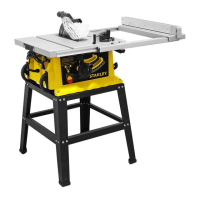
Fitting the table saw to the stand (see FIG. C1, C2)
There are four mounting holes on the base of the saw. 4
corresponding mounting holes are located on the top plane of
the stand. Put the table saw on the stand, match the holes on
the base of the saw with the holes on the stand, and secure
them with the 4 bolts (12) provided. DO fully fasten
Transportation (Fig C3)
Pull out the right side extension as the temporary handle to
transport the table saw on its wheels."
12
C1
12
C2
运 输( 图
C3
)
拉出右侧延伸部分作为临时手柄,并使用其在轮子上运输台锯。
uprights. Note that Part 2 should be positioned as shown in
Fig. B4. Connect Part 4 (top cross support) to the top of the
frame. Note that Part 4 should be positioned as shown in
Fig. B4.
Step 4
Now place and connect the ends of the top and center frame
supports to the frame. Take care to ensure that the supports
are positioned as shown in Fig. B5.
Step 5
Once you are satisfied that the frame is assembled correctly,
fully tighten ALL the bolts. Finally, assemble the 4 foot pads to
the bottom of each leg (see Fig. B6).
2. Assemble the stand’s legs
Step 1
Select the following parts:
2 x Part 1
1 x Part 3
1 x Part 5
Lay the parts together as shown in Fig. B1, B2, and B3. This
is best done by simply laying the parts loosely together on the
floor. Once you are satisfied that you have the parts correctly
laid together, start the fitting process.
Align the holes and secure with the bolts as shown in
Fig. B1.
DO NOT fully tighten the bolts, nuts and washers at this point.
Finger tight is sufficient.
Step 2
Repeat Step 1 so that there are two frames assembled.
Step 3
Select the following parts:
2 x Part 2
2 x Part 4
These will form the crosspieces between the previously
assembled frames. Lay the parts flat on the floor. Connect the
longer Part (2) and fix it to the frame in the center of the
B1
B2
B3
B1
5
3
2
4
B4
1
B6
5
1
4
B5
Handle assembly (Fig D)
Place washer (e), housing (b), washer (c) and hex nut (d) on
the bolt (a) to assemble the handle (11)
Riving knife set-up (Fig E, F, G)
WARNING! Disconnect the mains cable! The
setup of the riving knife (3) must be checked
before each use.
1. Set the saw blade (4) to the max. cutting depth, put it at 00
position and lock it
2. Remove the table insert (20) (Fig. E)
WARNING! For transport reasons, the riving
knife (3) was fixed in the lower position before
initial commissioning. Only work with the
machine if the riving knife (3) is in the upper
position. Fitting the riving knife (3) in the upper
position is as follows:
3. Loosen the locking handle (f) and push the riving knife (3)
in the upper position (Fig.F)
Fitting the table saw to the stand (see FIG. C1, C2)
There are four mounting holes on the base of the saw. 4
corresponding mounting holes are located on the top plane of
the stand. Put the table saw on the stand, match the holes on
the base of the saw with the holes on the stand, and secure
them with the 4 bolts (12) provided. DO fully fasten
Transportation (Fig C3)
Pull out the right side extension as the temporary handle to
transport the table saw on its wheels."
12
C1
12
C2
C3
将垫圈 (
e
)、外壳 (
b
),垫圈 (
c
) 和六角螺母 (
d
) 放在螺栓 (
a
) 上,
以组装手柄 (
11
)
uprights. Note that Part 2 should be positioned as shown in
Fig. B4. Connect Part 4 (top cross support) to the top of the
frame. Note that Part 4 should be positioned as shown in
Fig. B4.
Step 4
Now place and connect the ends of the top and center frame
supports to the frame. Take care to ensure that the supports
are positioned as shown in Fig. B5.
Step 5
Once you are satisfied that the frame is assembled correctly,
fully tighten ALL the bolts. Finally, assemble the 4 foot pads to
the bottom of each leg (see Fig. B6).
2. Assemble the stand’s legs
Step 1
Select the following parts:
2 x Part 1
1 x Part 3
1 x Part 5
Lay the parts together as shown in Fig. B1, B2, and B3. This
is best done by simply laying the parts loosely together on the
floor. Once you are satisfied that you have the parts correctly
laid together, start the fitting process.
Align the holes and secure with the bolts as shown in
Fig. B1.
DO NOT fully tighten the bolts, nuts and washers at this point.
Finger tight is sufficient.
Step 2
Repeat Step 1 so that there are two frames assembled.
Step 3
Select the following parts:
2 x Part 2
2 x Part 4
These will form the crosspieces between the previously
assembled frames. Lay the parts flat on the floor. Connect the
longer Part (2) and fix it to the frame in the center of the
B1
B2
B3
B1
5
3
2
4
B4
1
B6
5
1
4
B5
Handle assembly (Fig D)
Place washer (e), housing (b), washer (c) and hex nut (d) on
the bolt (a) to assemble the handle (11)
Riving knife set-up (Fig E, F, G)
WARNING! Disconnect the mains cable! The
setup of the riving knife (3) must be checked
before each use.
1. Set the saw blade (4) to the max. cutting depth, put it at 00
position and lock it
2. Remove the table insert (20) (Fig. E)
WARNING! For transport reasons, the riving
knife (3) was fixed in the lower position before
initial commissioning. Only work with the
machine if the riving knife (3) is in the upper
position. Fitting the riving knife (3) in the upper
position is as follows:
3. Loosen the locking handle (f) and push the riving knife (3)
in the upper position (Fig.F)
Fitting the table saw to the stand (see FIG. C1, C2)
There are four mounting holes on the base of the saw. 4
corresponding mounting holes are located on the top plane of
the stand. Put the table saw on the stand, match the holes on
the base of the saw with the holes on the stand, and secure
them with the 4 bolts (12) provided. DO fully fasten
Transportation (Fig C3)
Pull out the right side extension as the temporary handle to
transport the table saw on its wheels."
12
C1
12
C2
C3
d
c
e
a
11
D
b
分 料 刀 设 置( 图
E
,
F
,
G
)
警告!断开电源电缆!每次使用之前,必须检查分料刀
(3)
的设置。
1.
将锯片 (
4
) 设置为最大切割深度,将其置于
00
位置并锁定
2.
拆下锯台嵌件 (
20
)( 图
E
)
uprights. Note that Part 2 should be positioned as shown in
Fig. B4. Connect Part 4 (top cross support) to the top of the
frame. Note that Part 4 should be positioned as shown in
Fig. B4.
Step 4
Now place and connect the ends of the top and center frame
supports to the frame. Take care to ensure that the supports
are positioned as shown in Fig. B5.
Step 5
Once you are satisfied that the frame is assembled correctly,
fully tighten ALL the bolts. Finally, assemble the 4 foot pads to
the bottom of each leg (see Fig. B6).
2. Assemble the stand’s legs
Step 1
Select the following parts:
2 x Part 1
1 x Part 3
1 x Part 5
Lay the parts together as shown in Fig. B1, B2, and B3. This
is best done by simply laying the parts loosely together on the
floor. Once you are satisfied that you have the parts correctly
laid together, start the fitting process.
Align the holes and secure with the bolts as shown in
Fig. B1.
DO NOT fully tighten the bolts, nuts and washers at this point.
Finger tight is sufficient.
Step 2
Repeat Step 1 so that there are two frames assembled.
Step 3
Select the following parts:
2 x Part 2
2 x Part 4
These will form the crosspieces between the previously
assembled frames. Lay the parts flat on the floor. Connect the
longer Part (2) and fix it to the frame in the center of the
B1
B2
B3
B1
5
3
2
4
B4
1
B6
5
1
4
B5
Handle assembly (Fig D)
Place washer (e), housing (b), washer (c) and hex nut (d) on
the bolt (a) to assemble the handle (11)
Riving knife set-up (Fig E, F, G)
WARNING! Disconnect the mains cable! The
setup of the riving knife (3) must be checked
before each use.
1. Set the saw blade (4) to the max. cutting depth, put it at 00
position and lock it
2. Remove the table insert (20) (Fig. E)
WARNING! For transport reasons, the riving
knife (3) was fixed in the lower position before
initial commissioning. Only work with the
machine if the riving knife (3) is in the upper
position. Fitting the riving knife (3) in the upper
position is as follows:
3. Loosen the locking handle (f) and push the riving knife (3)
in the upper position (Fig.F)
Fitting the table saw to the stand (see FIG. C1, C2)
There are four mounting holes on the base of the saw. 4
corresponding mounting holes are located on the top plane of
the stand. Put the table saw on the stand, match the holes on
the base of the saw with the holes on the stand, and secure
them with the 4 bolts (12) provided. DO fully fasten
Transportation (Fig C3)
Pull out the right side extension as the temporary handle to
transport the table saw on its wheels."
12
C1
12
C2
C3
d
c
e
a
11
D
b
204
E
警告!由于运输的原因,在开始调试之前,将分料刀
(3)
固定在下部位置。仅当分料刀
(3)
处于上方位置时,才可
以使用机器。将分料刀
(3)
装在上方位置的步骤如下:
3.
松开锁定手柄 (
f
) 并将分料刀 (
3
) 推到上方位置(图
F
)
21
简体中文
 Loading...