This document is a service handbook for commercial and residential gas water heaters manufactured by State Water Heaters. It covers models SHE 50-100 NE, SHE 50-100 PE, GP650 YTPDT, GP650 HTPDT, and Series 120 & 121. The handbook provides troubleshooting procedures, installation considerations, pre-service checks, water heater construction, operation, and service information. Servicing should only be performed by a qualified service agent.
Function Description
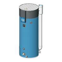
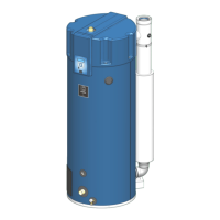
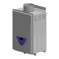
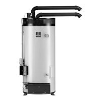
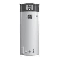
The water heaters covered in this manual are designed to provide hot water for commercial and residential applications. They utilize a helical-shaped coil heat exchanger submerged in the storage tank and a top-mounted, down-fired radial design burner. These are forced draft burners, meaning hot burning gases are forced through the heat exchanger under pressure and exit through the exhaust/vent connection at the bottom of the water heater. Air and fuel gas are drawn in by the Combustion Blower and Venturi. The Control System electronically regulates water temperature, manages heating cycles and ignition, and monitors various components like the ECO (energy cut out), Flame Sensor, pressure switches, and Temperature Probe. It also energizes the Combustion Blower, Igniter, and the 24 Volt Gas Valve.
Important Technical Specifications
- Models Covered: SHE 50-100 NE, SHE 50-100 PE, GP650 YTPDT, GP650 HTPDT, Series 120 & 121.
- Power Supply: 120 VAC (Volts Alternating Current) 1Ø (Single Phase).
- Maximum AC Amperage: Approximately 5.2 FLA (full load amps) during Igniter Warm Up.
- Gas Input: Rated at 100,000 Btu/hr.
- Elevation Certification: Up to 10,100 feet (3,078 meters).
- Operating Set Point Range:
- Commercial models: 90°F (42°C) to 180°F (82°C).
- Residential models: 90°F (42°C) to 160°F (71°C).
- Factory setting: 120°F (49°C).
- Differential Setting Range: 2° to 20°. Factory setting: 8°.
- Flame Sensing Current: Minimum 1.0 µA DC micro amps required to prove flame. Normal range is 8.0 µA to 12.0 µA with a clean Flame Sensor.
- Igniter Current: Minimum 0.5 AC amps required during Igniter Warm Up. New igniters typically measure between 90 and 120 ohms at 77°F (25°C); acceptable resistance is less than 200 ohms.
- Gas Valve: 24 Volt DC voltage valve, energized by 24 VAC from the CCB and rectified internally.
- Manifold Offset Gas Pressure (Natural Gas): 0.24" W.C. (0.056 kPa).
- Manifold Offset Gas Pressure (Propane Gas): 0.17" W.C. (0.042 kPa).
- Minimum Supply Gas Pressure (Natural Gas): 3.5" W.C. (0.87 kPa).
- Minimum Supply Gas Pressure (Propane Gas): 8" W.C. (1.20 kPa).
- Maximum Supply Gas Pressure (Natural Gas/Propane Gas): 14" W.C. (3.49 kPa).
- Gas Orifice Size (Natural Gas): 0.191".
- Gas Orifice Size (Propane Gas): 0.162".
- Pressure Switch Activation Pressures (with ± 0.05" W.C. tolerance):
- Blower Prover: +0.75" W.C. (normally open, closes on rise).
- Blocked Intake Air: -2.00" W.C. (normally closed, opens on fall).
- Blocked Exhaust: +2.00" W.C. (normally closed, opens on rise).
- Vent Pipe Equivalent Length (2 Inch Pipe): Max 40 feet (12.2 meters) with one 90° elbow.
- Vent Pipe Equivalent Length (3 Inch Pipe): Max 120 feet (36.6 meters) with one 90° elbow.
- Elbow Equivalent Length: Each 90° elbow = 5 linear feet; each 45° elbow = 2.5 linear feet.
- Maximum 90° Elbows: Six (6) for vent pipe, and six (6) for intake air pipe in Direct Vent.
Usage Features
- User Interface Module (UIM): Features an LCD display and five input buttons (up, down, and three multifunctional operational buttons).
- Desktop Screen: Default display showing manufacturer/model information, tank temperature (commercial models only), operating set point, current status (e.g., Heating, Standby), and animated status icons.
- Control System Navigation: Up/down buttons for menu navigation and setting adjustments; operational buttons for entering/exiting menus, selecting items, activating adjustment modes, and confirming/canceling changes.
- Status Icons: Visual indicators on the Desktop Screen for operational and diagnostic information (e.g., water temperature, blower energized, igniter energized, flame detected, fault conditions).
- Operating States: Displays current operational state (e.g., Standby, Pre-Purge, Heating, Fault).
- Control System Menus: Access to Temperatures (set point, differential), Heater Status (component states), Display Settings (units, backlight, contrast), Heater Information (elapsed time, burner on time, cycle count, software versions), Current Fault, Fault History, Fault Occurrence, and Restore Factory Defaults.
- Tank Probe Offset: Adjustable setting (-5° to +5°) to calibrate temperature sensing, improving precision or compensating for recirculation loops.
- Service Contact Information: A discrete menu allows installers/service agents to enter contact information for customers, which is displayed with fault/alert messages.
- iCOMM Compatibility: This model is iCOMM compatible for remote monitoring.
Maintenance Features
- Troubleshooting Procedures: Comprehensive guides for common fault conditions, including rough starting/operation, not enough hot water, and specific fault messages (AC Reversed, Temp Probe Open/Short, Flame Sensor Short, Flame Detect Error, Energy Cut Out (ECO), Blocked Air Intake, Blocked Exhaust, Blower Prover Failure/Open, Low Igniter Current, Ignition Failure, Communication Failure).
- Diagnostic Checks: The Control System performs diagnostic checks at the start of a heating cycle, verifying pressure switch and ECO contacts.
- Fault Messages: Detailed fault messages displayed on the LCD, indicating specific problems and locking out heating operation until corrected.
- Fault History: Stores a list of the last nine fault/alert messages with timestamps (cleared after 30 days).
- Fault Occurrence: Tracks the total number of times each fault condition has occurred since installation (saved indefinitely in CCB memory).
- Resetting the Control System: Power cycling (off for ~20 seconds, then on) can reset the Control System from a lock-out/fault condition, provided the underlying issue is resolved.
- Component Inspection and Replacement: Instructions for inspecting and replacing key components such as the Combustion Blower, Burner Assembly, Flame Sensor, Igniter, and Gas Valve.
- Gasket Replacement: Emphasizes the importance of replacing gaskets (silicone for blower, fiber for burner adapter/burner) during assembly removal/installation.
- Flame Sensor Cleaning: Recommends cleaning the flame sensor with ultra-fine steel wool to maintain proper flame sensing current.
- Igniter Current Test: Procedure to measure igniter amperage to verify it meets the minimum 0.5 AC amps requirement.
- Gas Pressure Test: Procedures to measure manifold offset and supply gas pressures using digital manometers.
- Pressure Switch Tests: Continuity tests (during standby and operation) and pressure tests to diagnose pressure switch malfunctions.
- Wiring and Connector Inspection: Critical reminder to visually inspect all wiring and connectors for damage, loose connections, or improper mating to prevent needless downtime and parts replacement.
- Ventilation and Air Supply Checks: Instructions to ensure adequate combustion air and proper venting, checking for restrictions or blockages in intake/exhaust piping.
- Grounding and Polarity Checks: Emphasizes the importance of correct power supply grounding and polarity to prevent Ignition Failure and AC Reversed faults.
- Tools Required: Lists necessary tools including hand tools, pipe wrenches, hex wrenches, digital manometers, digital multi-meter (with AC/DC voltage, ohms, DC micro amps, AC amp meter), and a 120 VAC plug-in outlet tester.