19 / 52
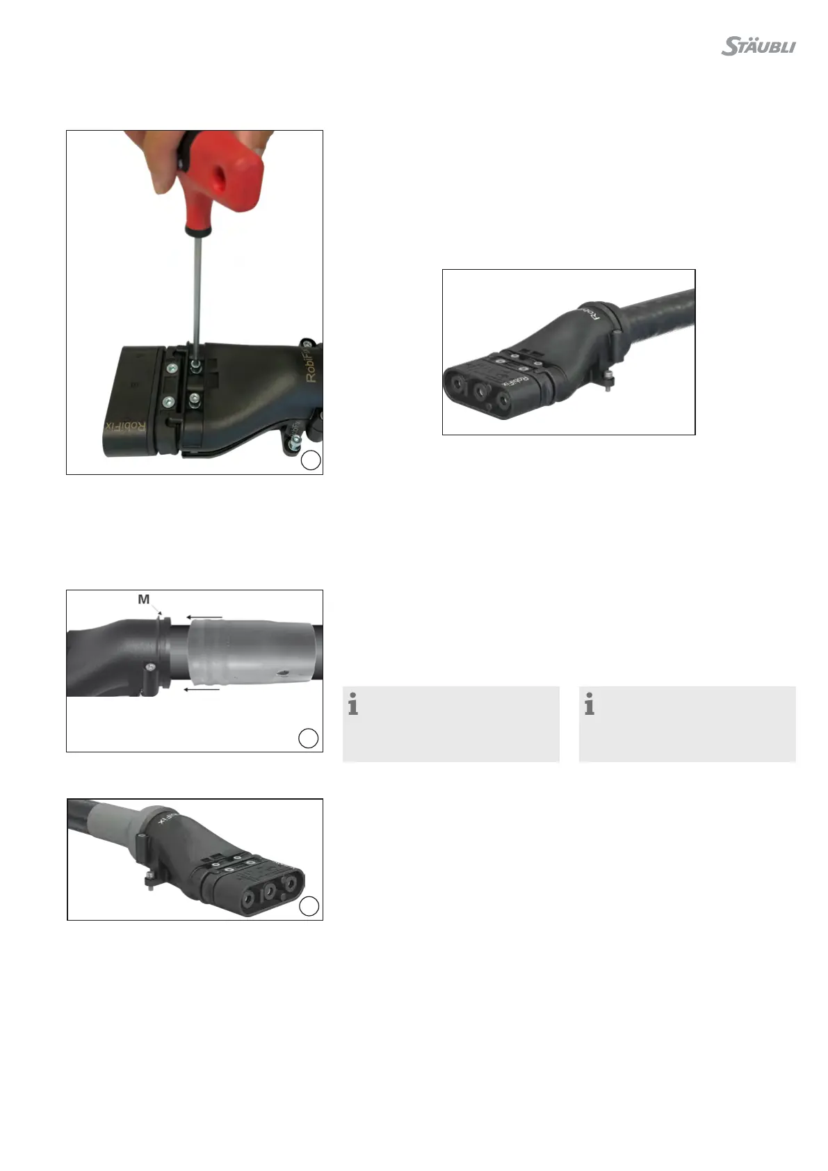
41
42
43
(ill. 41)
Poner la pieza superior del RobiFix ZEM
sobre la correspondiente pieza inferior
y presionar con fuerza en la zona de los
tornillos�
Apretar los tornillos con una llave dina-
mométrica de forma alterna�
Par de apriete: 5N m�
A continuación, apretar los tornillos de
la parte trasera�
(ill. 41)
Place RobiFix-ZEM-upper part on
RobiFix-ZEM-lower part and press
down firmly in area of screws�
Tighten screws alternately with torque
wrench�
Tightening torque 5N m�
Afterwards tighten rear screws�
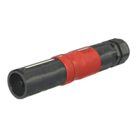
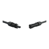
RobiFix-B��-ZEM con la junta-guía
FD50 montada�
RobiFix-B��-ZEM assembled with FD50�
RobiFix-B..-ZEM con
WST-TS150
RobiFix-B..-ZEM with
WST-TS150
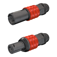
(ill. 42)
Colocar el tubo termorretráctil sobre la
ranura (M)� A continuación, retraer de
manera pareja sobre el cable y hacia el
interior de la ranura de posicionamiento�
El sello FD50 no es necesario�“
(ill. 42)
Position heat shrink tube over the
groove (M)� Then shrink evenly onto the
cable and into the locating groove�
Seal FD50 is unnecessary�
Nota:
Encontrará más información sobre
el tratamiento de piezas termorretrác-
tiles en las instrucciones de montaje
MA200 (www�staubli�com/electrical)
Note:
For further hints on the handling of
form shroud see Assembly instruc-
tions MA200
(www�staubli�com/electrical)
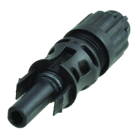
(ill. 43)
RobiFix-B��-ZEM con tubo termorretrác-
til montado�
(ill. 43)
RobiFix-B��-ZEM assembled with adhe-
sive coated heat shrink insulator�