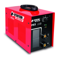
47.- TIG / LIFT ARC (Direct Current Electrode Negative) Connections
3
4
5
6
7
+
-
2
1
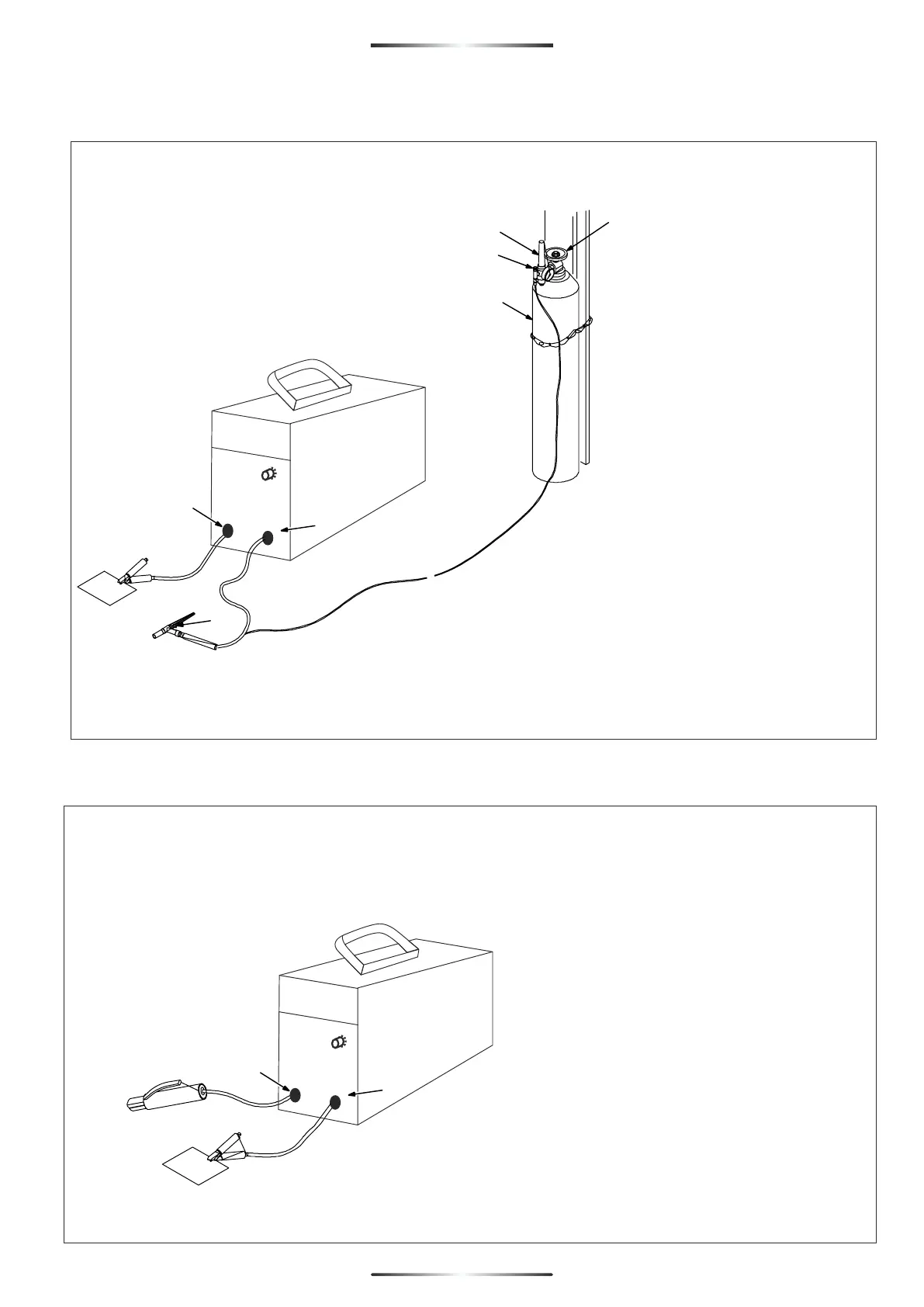
48.- Stick DCEP (Direct Current Electrode Positive) Connections
+
-
1
2
ENGLISH
24
24
1 Positive (+) Weld Output Terminal
Connect work lead to positive
weldoutput terminal.
2 Negative (−) Weld
Output Terminal Connect TIG torch to
negative weld output terminal.
3 Gas Cylinder
4 Cylinder Valve
Open valve slightly so gas flowblows dirt
from valve. Close valve.
5 Regulator/Flowmeter
6 Flow AdjustTypical flow rate is (15
cubic feet perhour) 7.1 liters per minute.
C o n n e c t t o r c h g a s h o s e t o
regulator/flowmeter.
7 Gas Valve
Valve controls gas preflow andpostflow.
Open valve on torch justbefore welding.
1 Negative (−) Weld Output Terminal
Connect work lead to negative weld
output terminal.
2 Positive (+) Weld Output Terminal
Connect electrode holder topositive weld
output terminal.