!
User Manual
Control Panel SS I
Control Panel SS I
Control Panel SS II
Temperature sensor
Locknut for temperature
sensor base
Drill
10
1cm
Ground
1.2~1.5m
(Fig.1) (Fig.2)
(Fig.3)
Temperature sensor
base (optional)
To
ensure horizontal
installation of the controller, use a
level if necessary.
Important:
Control Panel SS II
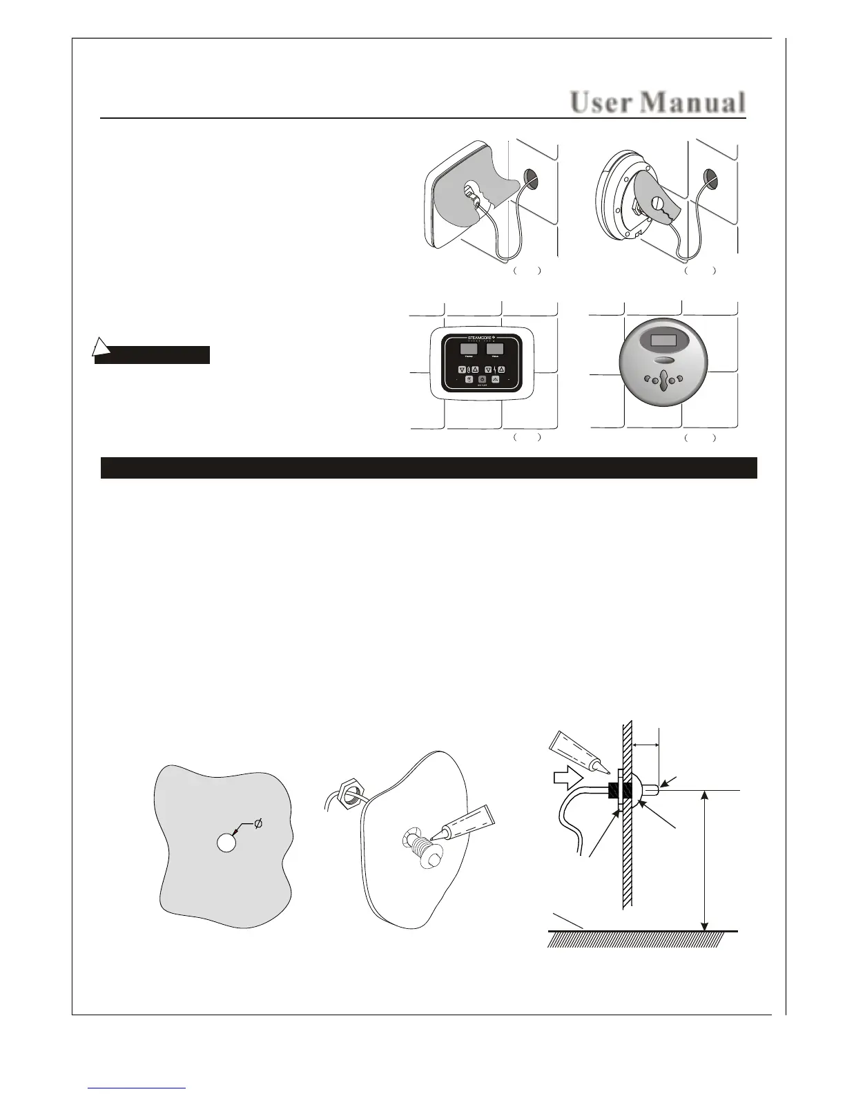
Temperature sensor installation(only for SS I )Control Panel
STEP FIVE
STEP SIX
Remove the paper on the back side of the controller. To
expose the 3m adhesive tape. To achieve good adhesion
to the wall finish make sure it is clean and dry.
Locate the display screen in the direction of 12 o'clock,
and press the controller firmly to the wall finish.
1. The position of the temperature sensor for the SSI controller should be within a range of 4.5 - 5 ft (1.2M - 1.5M) from
from the steam room finish floor. Try to avoid installing in the vicinity of the steam nozzle(s) or the opening side of the
steam room door.
2. As shown Fig1, drill a small hole 3/8 inch (10mm) in the selected location.
3. Apply a bead of silicone along the edge of the back of the sensor base.
4. The sensor holder and nut is no longer supplied nor required.
5. Place sensor chrome tip within steam room and place small bead of silicone to create seal and hold sensor into place.
The temperature sensor should be installed by extending about 0.5 inch (1cm) from the front of the steam room
to make sure the speed and accuracy of temperature control.
18