!
!
Important:
1. Please consult your distributors of building materials like acrylic, fiber glass or other
anti-heat sheet about the installation position of steam nozzle. It is suggested that MS-
103412 anti-heat material can be used.
2. In the entire steam room, it is required that steam must not leak out. The pipes, its
accessories and the holes in the wall should be airproof by applying silicone so
that no steam will enter the holes in the wall.
Attention:
User Manual
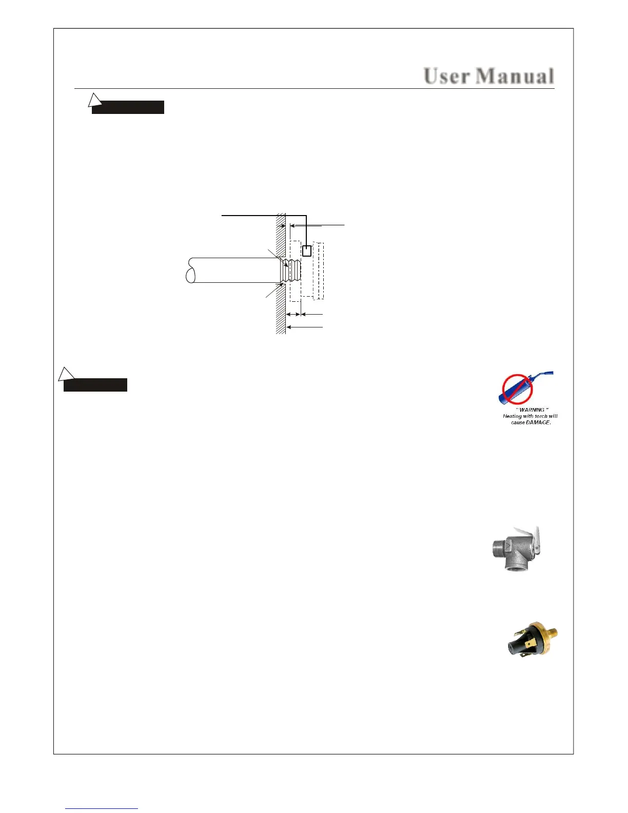
DO NOT HEAT AUTO FILL / DRAIN VALVES WITH TORCH DURING INSTALLATION.
Aroma Essence Reservoir
(apply a few drops prior to heating)
If non-heat-resistant material such as acrylic
is used a wall material, create a gap of no less
then 1.4" and fill with silicone.
Inside wall of steam room.
Use silicone to fill in the gaps in the wall
to achieve the proper water proofing
and damp proof effect.
Apply Silicone
The drain pipe should not incline to prevent gravity flow of draining water.
This may cause damage, leakage or malfunction to intake/drain solenoid valves
DRAIN PIPE: (1/2 inch diameter)
Steam generators up to 9 KW are equipped with an auto drain solenoid valve. The steam generators 10.5 KW and higher
are also equipped with an auto drain solenoid valve, plus an additional manual drain port that is capped. The manual drain port
is to remain capped at all times. This secondary port is for back up manual draining if required for
maintenance use only.
SAFETY PRESSURE RELIEF VALVE: Rated 15 psi.
1. Pressure relief valve is a safety device in order to prevent too much pressure build up within
the steam generator. Build up of pressure can be created by many different reasons; steam line
line blockage, undersized steam line pipr diameter, steam line traps, or vandalism. This build up
of excessive back pressure may cause the auto & manual high temperature limiting switches to
trip and cut power to the heating elements to stop producing steam.
2. The steam generator is shipped with plastic caps over the steam outlets, these are to be removed
and discarded only when making connection to the steam lines. The purpose of these caps is to
avoid any particles getting into the boiler tank while installing or handling the steam generator during
installation.
3. Steam bath generators that are 18 KW and Higher will have a factory installed pressure switch. This
pressure switch will cut power to the steam generator heating elements when the internal steam pressure
within the boiler tank or steam line(s) reaches over the manufactures recommended limit. The switch will
reset automatically when the excessive pressure has been substantially reduced. This will re-occure until
the cause of excessive pressure has been rectified. Usuall causes are listed in point 1.
4. Safety pressure relief valve is an automatic system that is actuated by pressure in order to prevent steam pressure
increasing in the interior of the generator. The pressure limit range of the saftey is 15 PSI and the pressure will begin
to decrease if pressure should come over this value. If it is allowed by local codes, provide the safety valve with exterior
drainpipe. Do NOT dismantle the pressure relief valve while generator is in operation. To maintain the proper automatic
operation of the safety valve, make sure the safety valve connection pipe is smooth.
4
 Loading...