!
Ampere Meter
!
The data provided above are for 240V(1PH) and 208V(3PH). Consult the manufacturer for
three-phased electricity or electric voltage of other specifications. Within the steam generator,
install an independent circuit breaker so as to provide an electricity supply with
overflow protection and electricity leakage protection (ground fault interrupter.)
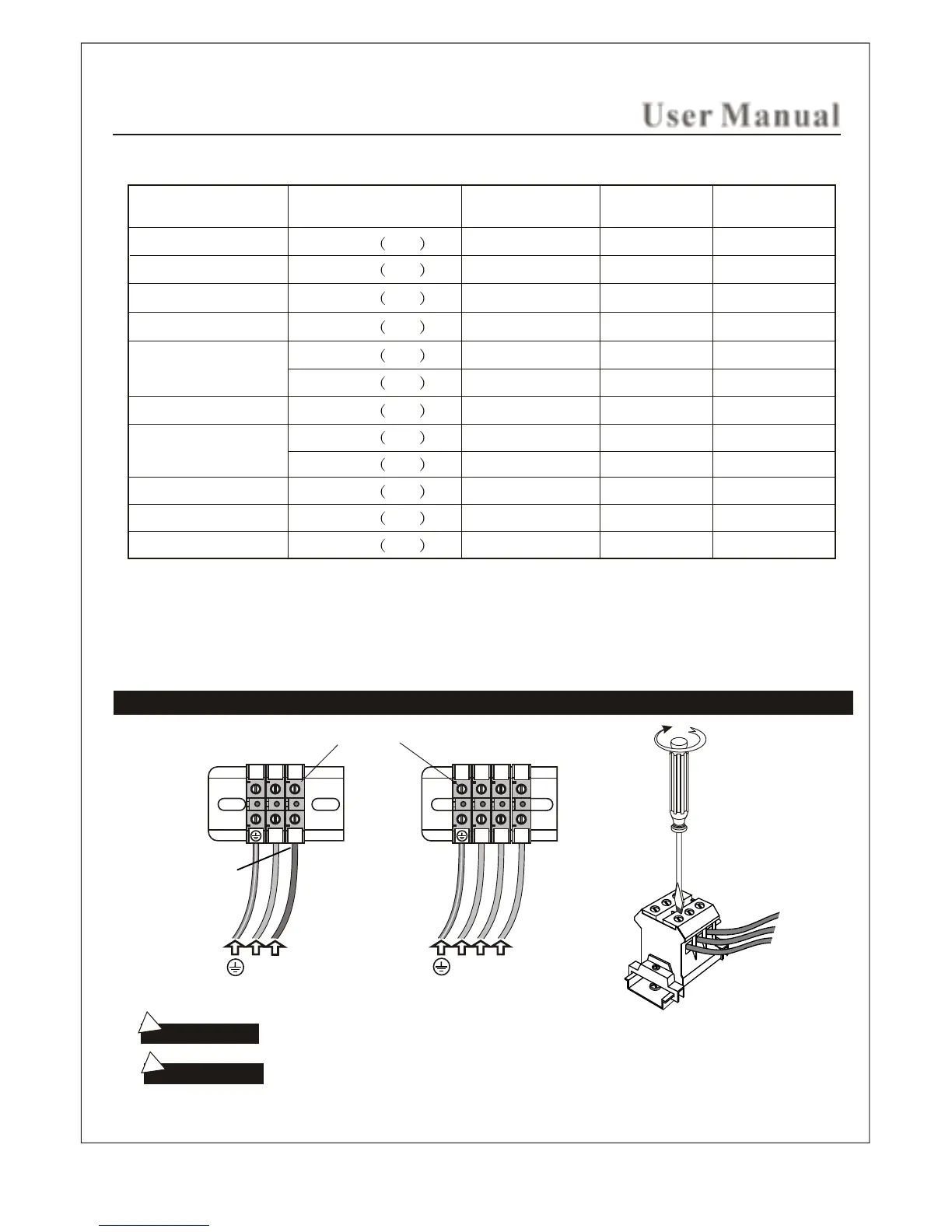
Power Supply Wire Connection
To avoid damage to the equipment, do not connect strong electric
current to the component directly.
This drawing is for explanation only. For actual installation, refer to
national and local electricity consumption codes by professional licensed electricians.
Attention:
Warning:
240V~ 1PH
240V~ 1PH
240V~ 1PH
240V~ 1PH
240V~ 1PH
208V~ 3PH
240V~ 1PH
240V~ 1PH
208V~ 3PH
12.5A
18.75A
25A x 3
Type
Applicable space of
3
the room (m )
Electricity
supply
Electric
current (A)
L1
L2
L3
(240V~ 1PH)
(208V~ 3PH)
L1
L1 L2 L3
Power connection terminal
User Manual
3kW
4.5kW
6kW
7.5kW
9kW
10.5kW
12kW
13.5kW
15kW
18kW
208V~ 3PH
208V~ 3PH
208V~ 3PH 18~22
15~20
14~18
12~15
12~15
10~13
8~12
8~12
6~10
5~8
4~7
3~6
25A
31.25A
37.5A
43.75A
50A
33.3A x 3
37.5A x 3
41.7A x 3
50A x 3
L2
L1
L2
The total connected load should not be more then 80% of the rating of the overcurrent devices.
European Connection
( L2 = N "Neutral")
7