2 Identification
General information
Feature Description
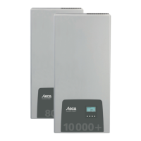
Type StecaGrid 8000+ 3ph / StecaGrid 10 000+ 3ph
Issue version of the manual Z02
Manufacturer's address See Section 17, p. 80.
Certificates See p. 121 onwards and
www.stecasolar.com StecaGrid 8000+ 3ph / 10 000+ 3ph
Optional accessories • StecaGrid Vision remote display, Steca order no. 737.421
• External data loggers:
– StecaGrid Monitor, Steca order no. 738.424
– WEB‘log from Meteocontrol
– Solar-Log from Solare Datensysteme
• Grounding terminal, Steca order no. 743.012
• Termination plug, Steca order no. 740.864
• Opposing contacts for Multi-Contact MC4 DC connections:
– Plug: Steca order no. 719.621
– Socket: Steca order no. 719.622
• Safety sleeve for Multi-Contact MC4, Steca order no. 742.215
• AC plug for cable diameter of 15 ... 18 mm
2
, Steca order no. 741.038
Tab. 1: Identifying characteristics of the inverter
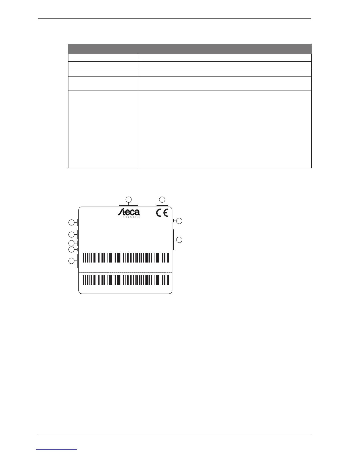
Type plate
1
2
9
4
6
3
5
7
8
Voltage: 350 - 700V, max. 845V
Current: max. 32A
Voltage: 3x400V, 50Hz
Current: max. 16A
Power:
max. 10300W,
10000W for
setting Belgium
IP classification: IP 54
DC Input: AC Output:
Manufacturer:
Art. number: 742.762
Model: StecaGrid 10000+ 3ph
S/N:
S/N:
742762XA001155550005
742762XA001155550005
Made in Germany
According to: VDE 0126-1-1
VDE AR N 4105
Serial number as a barcode and in plain text
Degree of protection
Grid-monitoring standard used
Technical data of the DC inputs
Item number and product designation
Steca logo
CE symbol
Country of manufacture
Technical data of the AC outputs
Fig. 3: Type plate (example)
For the position of the type plate, see Fig. 5, p. 47.
Display
The correct version of the manual matching the software is shown under the Information/System
info menu item in the display. The optionally available StecaGrid Vision remote display also shows
this version information; more information on this is provided in the StecaGrid Vision operating
instructions.
43
744.378 | 12.13
EN