11
742.110 | 14.50
EN
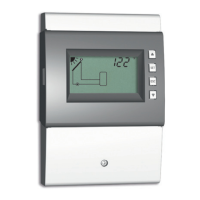
Display Legend Terminal layout
1 swimming pool, 1 collector array
R1
T1
T2
T1: Collector array sensor
T2: Swimming pool sensor
R1: Solar circuit pump
1,
2,
R1, N, PE (0-10 R1,
1)
)
Tab. 1: Terminal pin assignments of the solar power systems
1)
Terminal pin assignments for 0–10 V-controlled high-efficiency pumps: The power supply must
be connected to output R1 (N, PE), the control cable for the pump electronics must be con-
nected to 0-10
R1 and .
5 Commissioning the device for the first time
Danger
Risk of death by electrocution! Be sure to perform all the measures listed in section 4
before starting the first commissioning.
Notes
• After commissioning the controller for the first time, it is configured in such a man-
ner that it can be used in most applications without changes.
• After completing the first commissioning, later recommissioning is not necessary.
• The following steps must also be performed after the device has been reset to the
factory settings.
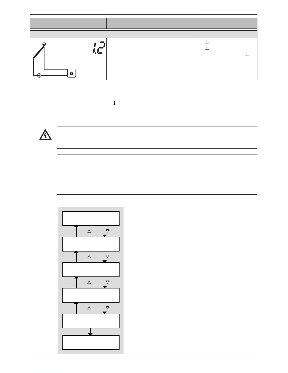
Overview
Time
System
Pump R1
Type / minimum speed
Functions
ESC /
ESC /
ESC /
Operation mode Off is
switched on.
ESC /
OK
SET
The first time the controller is switched on, the follow-
ing settings are made via a guided configuration process
(Fig. left):
• Time
• System (hydraulic variant)
• Type (Standard/high-efficiency pump) and minimum
speed of the connected pumps (not System 0.1)
• Functions
Values can be changed later within the guided configura-
tion process. The following applies:
• /ESC/ navigate blockwise forwards and back-
wards
(Fig. left: = forwards; ESC/ = back).
• Navigation (with /ESC/) is always possible after
completion of a block.
• Later modification of a block is initiated using the
SET button.