SteFly Canopy Flasher Manual Version 1.2 6
3.3
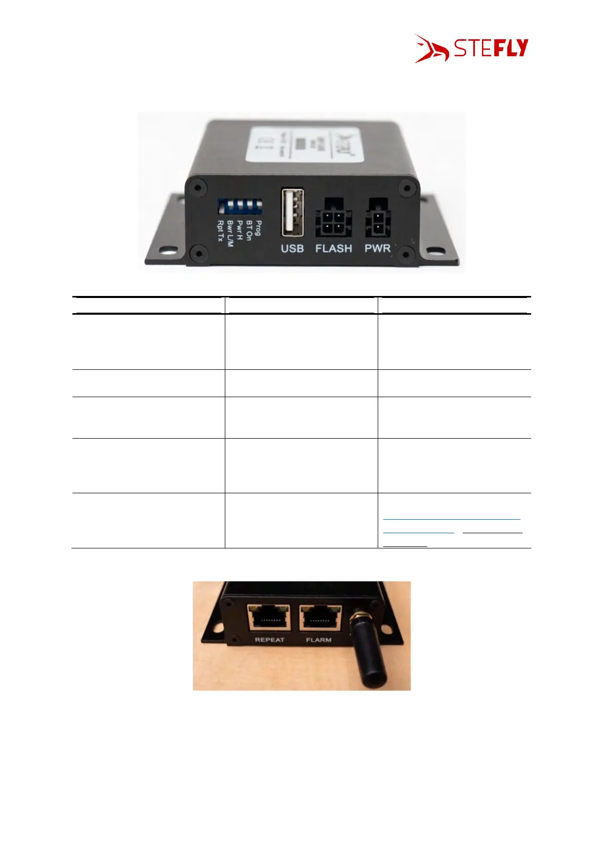
DIP Switches
The DIP switches allow some individual settings. In default status all DIP switches are up.
passing data (TX & RX) across
from the FLARM to the REPEAT
connection (repeater mode)
the transmit line to the FLARM
is from the Control Box (e.g.
XCSoar via Bluetooth) itself,
not the REPEAT
low or medium power
(according to setting of “Pwr
L/M” DIP switch)
high power mode, regardless
of “Pwr L/M” setting
Bluetooth on, connect to send
position / FLARM data to
mobile devices with XCSoar /
SeeYou Navigator
only for updates (see chapter
Change of Baud Rate / Update
the Control Box); Flasher is not
operating
3.4
Status LEDs of the Control Box
The Control Box has four status LEDs, positioned above the RJ45 connectors:
• LED1 (left): Valid GPS data received (off = no fix / on = 3d fix, on ground / flash[1's] = 3d fix,
airborne) <<< note actual flasher will only flash when airborne
• LED2: BT connected (turns on when BT connected)
• LED3: Activity (flashes when data present)
• LED4 (right): Connected (turns on when RS232 connection present)