similarly qualified person in order to avoid a
hazard.
Transport damage
Your Poolrunner was packed carefully for the
transport. Please ensure when taking over
that the packaging is in an undamaged condi-
tion and all parts are in the package. If you
have ordered the package by mail, make sure
that the delivery is complete. Transport dam-
age must immediately be reported to the car-
rier (transport company or parcel). The re-
sponsibility for damages during transit is the
transporter, the supplier is not responsible.
Warranty
Warranty in relation to operation safety and
reliability is only accepted from the manufac-
turer under the following conditions:
The pool cleaner is operated according
to the specifications of the user.
For repairs, only original spare parts
are used (wearing parts are not subject
to warranty).
Consequential damages
For damage to the product, caused by failure
to follow the manuel recommendations, we
can not pay.
Position the power supply
The power supply of the device should be
appropriately positioned to allow the cleaner
to reach all corners of the basin. In order to
avoid any accident/damage, the power supply
unit should be steadily placed and fixed at a
minimum distance of 3.5m from the pool
edge.
Specifications:
Input voltage: 230 VAC
Frequency: 50 Hz
Output voltage: DC (direct current) 24 V
Input power: 150 W
Output power: 120 W
Working cycle: 1 h. / 1,5 h. / 2 h. / 2,5 h.
Cable lenght: 12 m
Maximum cleaning area in the swimming pool: 100 ㎡
Filtering capacity: 15 m³/h
Filtering capablity: 150 μm
Working temperature (water): 10°C - 32°C
Creeping speed: 15 - 18 m/min
Water resistance class: Cleaner: IPX8, power control box: IPX4
Ambient temperatur: 10°C - 40°C
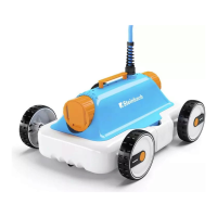
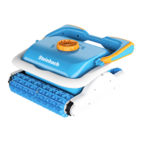
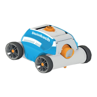
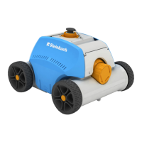
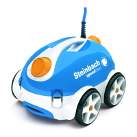
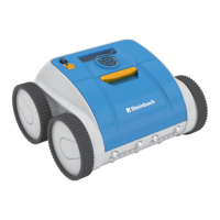
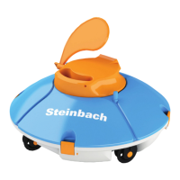
Cleaner Structure, Figure 1
Connecting cable, Figure 2,3,4
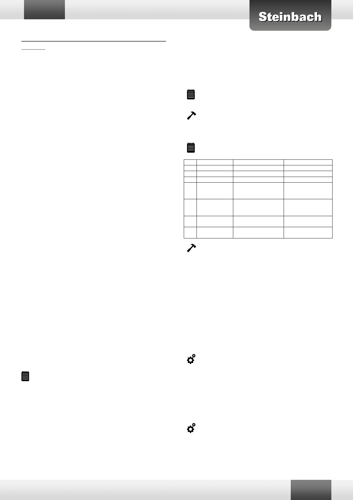
Description of control panel, Figure 5
To move the clean-
er to a certain loca-
tion
Cleaner starts run-
ning in automatic
program
Display of the se-
lected working time
Display of the set
pool size
Function of jet propulsion, Figure 6
Each on the front and on the back of the cleaner there are two ad-
justable control nozzles for the drive in the water. The sucked foul
water is first cleaned through the filter bag and then used for the
drive for the cleaner above the thrusters. The nozzles are adjustable,
depending on the size and pool type, to achieve the best cleaning ef-
fect.
Recommended nozzle settings:
High speed / less cleaning (with low pollution) Figure 7,8,9,10
Slow speed / high cleaning efficiency (moderate to heavy contami-
nation) Figure 11,12,13
The above are recommending settings and operator can select a
proper nozzle direction based on above principle actual pool situa-
tion.
Commissioning
Since you have made your settings, you can put the cleaner careful-
ly and slowly into the pool. Please refer to the following pictures as
the cleaner may be best placed in the pool. Figure 14,15,16
The cleaner must always be committed or removed to the pool that
the underside of the cleaner facing the pool wall, to avoid possible
scratches on the pool surface. Figure 17,18
IMPORTANT! Figure 19,20
Care and Maintenance
Cleaning the filter bag
Unfold the retaining ring and open the cleaner. Figure 21,22
Press the buckle on the base of the cleaner and take off the filter
cartridge. Figure 23,24
 Loading...