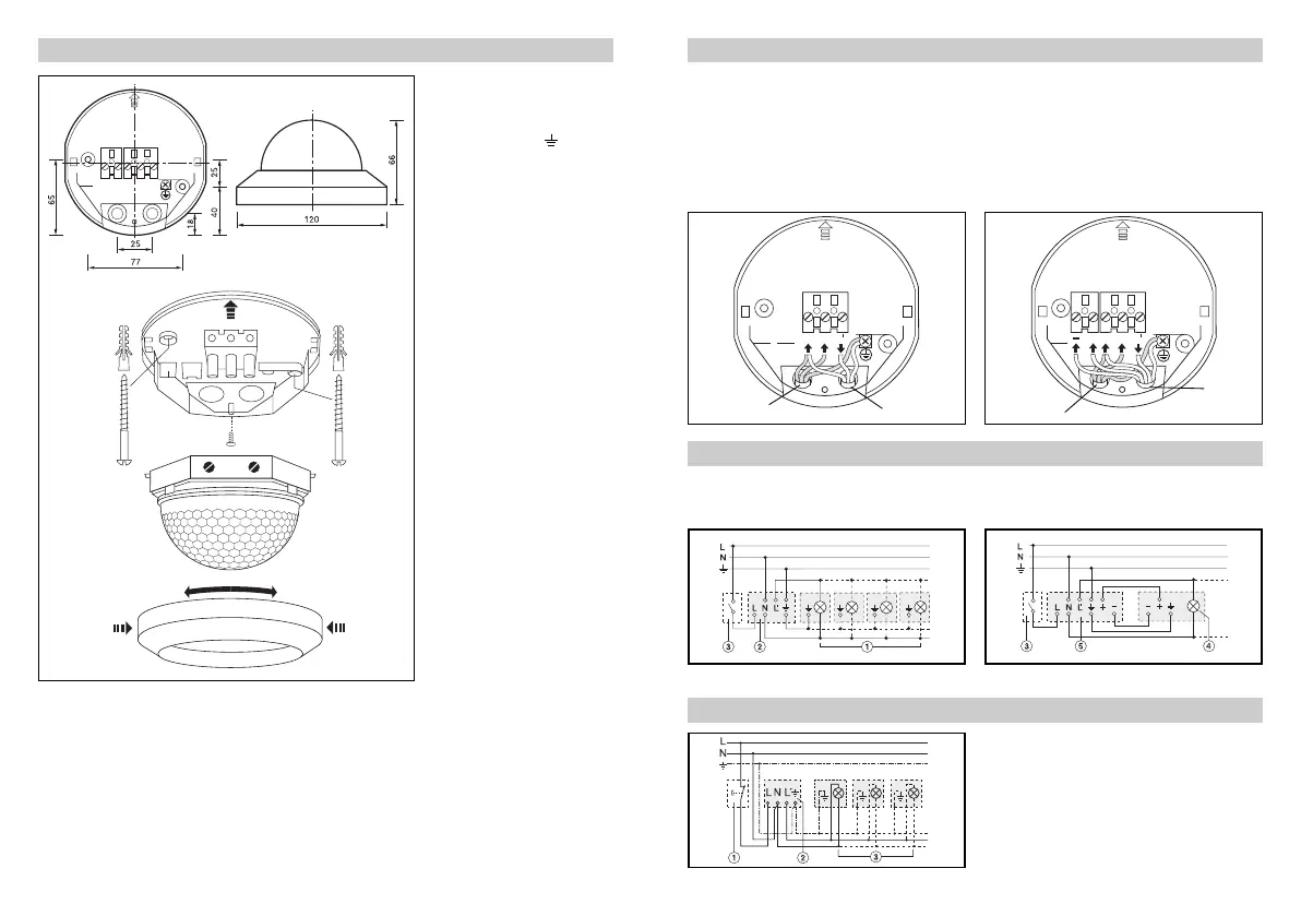
Electrical installation/automatic mode
Wiring example/manual switch-off
Wiring example semi-automated BLS T
BLS / BLS T
BLS BLS D / BLS DF
BLS D / BLS DF
In selecting the wiring leads, the
wiring regulations according to
VDE 0100 must be complied
with (see safety warnings on
page 12). The following applies
for wiring of the BLS D and
BLS DF: According to VDE 0100
520 sect. 6, a multiple lead may
be used for wiring between the
sensor and electronic ballast,
containing both the mains volt-
age leads and the control leads
(1–10 V) (e.g. NYM 5 x 1.5
2
).
The mains supply lead must
be no greater than 10 mm in
diameter.
The clamping range of the
mains terminal is designed for
a maximum of 2 x 1.5 mm
2
or
1 x 2.5 mm
2
.
15
If it is to be possible to delib-
erately switch off the auto-
matic function of the sensor
manually, a conventional
switch is to be positioned
upstream from the sensor.
1) Light group, 2) BLS, 3) External switch
1) Break-contact button, 2) BLS T, 3) Load, lighting
4) Light with dimming electronic ballast, 5) BLS D / BLS DF
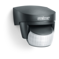
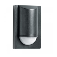
Assembly/Installation
Installation procedure
1. Pull off the decorative
ring by pressing lightly on
the sides and simultaneous-
ly turning downwards.
2. Unscrew the
locking
screw.
3. Pull the sensor enclosure
off the mounting plate
in the direction of the
arrow
.
4. Install the mounting plate
under the ceiling using the
enclosed screws and dow-
els.
5. Perform wiring (see Electri-
cal installation).
– Neutral conductor N
– Phase L
– Switched phase L
– Earth conductor (protective-
earth conductor)
– Control output +
– Control output –
– (only BLS D and BLS DF)
For surface wiring, the groove
on the decorative ring is to be
pierced and the cable is to be
introduced from the side.
16. Push-fit the sensor hous-
ing on to the mounting
plate from the side
(against the direction of
the arrow)
.
17. Screw in the locking
screw
.
18. Perform a function test
and adjust the detection
zone (see pages 16 and 19).
19. Adjust the switch-off delay
and brightness setting on
the front of the enclosure
(control dial) (see Func-
tions p. 17, Adjustments
section).
10. Apply the decorative ring
(clip in place). (Shrouds
are fixed with the decora-
tive ring).
14
Mains lead
Light with
dimming
electonic ballast
(e.g. NYM 5 x 1.5
2
)
Mains lead
e.g. NYM 3 x 1.5
2
Light
LuxMaster_10spr 27.08.2008 13:32 Uhr Seite 16