Home
STEYR MOTORS
Engine
SE266E40
STEYR MOTORS SE266E40 Service Manual
274 pages
Manual
Specs
Ask a question
To Next Page
To Next Page
Loading...
General
1/65
Z001138-1_20
13-02-01
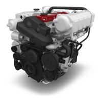
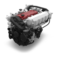
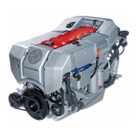
STEYR TURBO DIESEL ENGINES
Steyr Marine Engine Family 2012
SERVICE MANUAL
Z001138-0
1
st
Edition
February 2013
S
T
E
Y
R
M
O
T
O
R
S
G
m
b
H
www.steyr-motors.com
I
m
S
t
a
d
t
g
u
t
B
1
,
A-4407 Steyr-Gleink,
AUSTRIA
2
Table of Contents
Default Chapter
9
Table of Contents
9
Ageneral Remarks
11
A 1 Model and Serial Number
11
A 2 Documentation
12
A 3 Technical Data and Overview
13
A 3.2 Overview Engine M16 TCA
22
B Specification
23
B 1 Fuel Requirements
23
B 2 Motor Oil
25
C Maintenance and Service
26
C 1 Trouble Check Chart
26
C1 Trouble Check Chart Continued
27
Service- and Maintenance Schedule
30
D General Information
33
D 1 Electronic Engine Management System
33
Diagnostic System
37
Operation after Break - in
42
Extended Storage Preservation Procedure
42
E Quality Guidelines for Repair
44
E 1 Spare Part Specification
44
E 2 Workshop Profile
44
E 3 Nomenclature
45
E 4 si - System
47
E 5 Abbreviations
48
F Operating Material and Information on Disposal
49
F 1 List of Operating Material
49
F 2 Disposal of Automotive Waste Products
50
G Notes on Safety
51
G 1 General Notes on Safety
52
G 2 Guidelines for Damage Prevention
52
G 3 Legal Rules
52
G 4 Safety in the Use of Operating Material
53
G 5 Measures in Case of Accidents
53
H Tightening Torques
54
H 1 Listing of Tightening Torques
54
H 2 General Tightening Torques
60
H 3 Testing of Torque Wrenches
61
H 4 Non-Destructive Material Testing
61
H 5 Use of Adhesive and Sealing Materials
61
H 6 Solvent-Free Sealing Materials
61
I Wear Limits
64
I 1 Adjustment Information for Service and Maintenance
65
Engine Timing (Measured with Dial Indicator No. 2300899/0)
65
Tension Timing Belt (Measured with Tool VR00515/0)
65
Start of Fuel Delivery on the Unit Injectors (Measured with Dial Indicator No. 2300899/0)
65
Valve Clearance (Measured with Tool No. 2300712/3))
65
Engine Timing, Engine Mount
70
Lock Crank Shaft (Piston No. 1 at TDC)
70
Camshaft Housing Cover and Seal
73
Remove Timing Belt
82
Replace Engine Bracket
93
Cylinder Block
94
Replace Valves
94
Adjust Valve Clearance
96
Replace Valve Guide
97
Replace Pressure Regulating Valve for Oil Cooling Jet
98
Replace Stud Bolt for Unit Injector
99
Replace Dowel Pin for Positioning of Unit Injector
100
Replace Dowel Pin for Positioning of Camshaft Housing
101
Replace O-Ring at Oil Entry to Block
102
Mount Frame Seal
103
Crankshaft, Bearing, Vibration Damper
105
Replace Crankshaft
105
Replace Gear for Oil Pump Drive
109
Flywheel
110
Replace Flywheel
110
Piston and Connecting Rod
111
Dismantle Piston and Connecting Rod
111
Camshaft, Housing, Valve Gear
113
Replace Camshaft Housing
113
Replace Gas Stem Gasket (on Engine Assembly)
117
Replace Control Rack
119
Replace Camshaft
121
Replace Eccentric Shaft
122
Excentric Shaft
124
Replace Radial Shaft Seal of Camshaft
124
Replace Cam Follower
125
Replace Retainer of Cam Follower
126
Replace Valve Adjusting Element
127
Engine Housing, Oil Pump, Oil Suction Pipe
128
Replace Engine Housing
128
Replace Rear Ring Carrier
134
Replace Rear Radialshaft Sealing Ring
135
Replace Oil Pump (Front Ring Carrier)
136
Replace Oil Suction Pipe/ Oil Return Pipe
138
Intake Manifold/ Exhaust Manifold
139
Remove Intake Manifold
139
Mount Intake Manifold
141
Disassemble Exhaust Manifold Complete with Turbo Chargers
142
Mount Exhaust Manifold
143
Engine Oil Cooler
145
Replace Engine Oil Cooler
145
Change Motor Oil (General)
146
Fuel System
154
Fuel System
155
Fuel System
157
General Schematic
157
Functional Description
157
Unit Injector
159
Air System M16 VTI
160
Exhaust Pipe and Muffler MARINE 2012
161
Schema - Variable Geometry Turbochargers
162
Fuel Pump, Unit Injector, Lines
164
Replace Fuel Pump (Example)
164
Disassembly and Assembly of Unit Injector
166
Fix Control Rack
175
Adjust Control Link (Injection Quantity)
176
Release Fixing of Control Rod
177
Adjustment of Unit Injector - Start of Fuel Delivery
178
Exchange Pressure Check Valve at Fuel Outlet on Block
181
Turbo Charger
182
Replace Variable Geometry Turbochargers (VGT)
182
Check Bearing Clearance (Example)
186
Control Solenoid, Injection Timing Device (ITD)
187
Remove Control Solenoid
187
Install Rack Control Solenoid
188
Replace Potentiometer, Indication of Control Rack Position
189
Remove Injection Timing Device (ITD)
191
Install Injection Timing Device (ITD)
193
Change Fuel "Pre-Filter" and "Fine-Filter" (General Description)
194
Replace Glow Plug
196
Measurement of Compression Pressure
197
Fuel System Check
198
Manual Injection Test Method
198
Manual Check of Unit Injector Without Tool No. VR 00148/0
200
Disengagement Methode of Injection
201
Air Bubble Formation in Fuel System (Example)
202
Functional Description Engine Cooling Circuit
210
Error Detection Cooling System
212
Check Points for Problems in Cooling System
213
Component Checks of Engine Cooling System
214
Drain the Coolant from Engine
217
Fill Cooling System (Example)
218
Pipes, Thermostat
218
Coolant Pipes and Hoses
218
Exchange Thermostat
219
Replace Coolant Supply Manifold
220
Coolant Pump
221
Exchange Coolant Pump
221
Install Coolant Pump
224
Generator
233
Exchange / Replace Alternator
233
Starter Motor
237
Replace Starter Motor
237
Check Starter Motor (Principal Example)
239
Cables, Wiring Harness - General
241
Battery Cable Lengths and Cross-Sections
241
Engine Harness
242
Wiring Diagram - E-Box Wiring Diagram 2181123-0
244
Wiring Diagram - E-Box Wiring Diagram 2181134-0
245
Wiring Diagram - External E-Box Diagram 2181141-0
246
Wiring Instrument Harness / Marine
247
Warning and Parameter Limits from Engine Management System
249
Description to Circuit Diagram
250
Electronics - General
251
Electronic Engine Management System
252
Diagnostic System
253
Principle Service Code Table
254
Configuration Engine ECU-M1CU3 with Connector A1
258
Potentiometer Accelerator and Voltage Regulator
260
Potentiometer Accelerator 2180847-0, B09
260
Voltage Regulator 24V-12V Equalizer 2179789-0
261
Actor and Sensor
262
Component Configuration Engine
262
Calibration of Rack Position
263
Replace Senders, Sensors
265
ACT - Air Charge Temperature Sensor, B07
265
ECT - Engine Coolant Temperature Sensor, B06
265
RPM - Speed Sensor, B03
265
MAP - Manifold Absolut Pressure Sensor, B04
266
Rpos - Sensor for Rack Position, B01
266
LPS - Lubricant Pressure Sensor, B05
266
ITP - Injection Timing Position Sensor, B02
267
VTG - Vane Actuator, X25
267
MET- Manifold Exhaust Temperature Sensor X21
268
WIF - Water in Fuel Sensor
268
T2- Compressor Outlet Temperature Sensor
269
EXT - Exhaust Gas Temperature Sensor
269
Connectors, Helpful Hints
270
Connectors, Assembly Instructions
271
Battery
273
Other manuals for STEYR MOTORS SE266E40
Operation, Maintenance And Warranty Manual
134 pages
Need help?
Do you have a question about the STEYR MOTORS SE266E40 and is the answer not in the manual?
Ask a question
STEYR MOTORS SE266E40 Specifications
General
Number of Cylinders
4
Fuel System
Common rail direct injection
Cooling System
Liquid-cooled
Engine Type
4-stroke diesel engine
Displacement
2.1 l [128 cu in]
Related product manuals
STEYR MOTORS SE236E40
134 pages
STEYR MOTORS SE286E40
134 pages
STEYR MOTORS SE156E26
134 pages
STEYR MOTORS SE164E40
134 pages
STEYR MOTORS M094K33
329 pages
STEYR MOTORS MO256H45
114 pages
STEYR MOTORS MO236K42
114 pages
STEYR MOTORS MO286H43
114 pages
STEYR MOTORS M0144M38
329 pages
STEYR MOTORS MO144M38
134 pages
STEYR MOTORS MO114K33
120 pages
Marine Engine 2012 Series
274 pages