10 | DHC-E WWW.STIEBEL-ELTRON.COM
INSTALLATION
TECHNICAL DATA
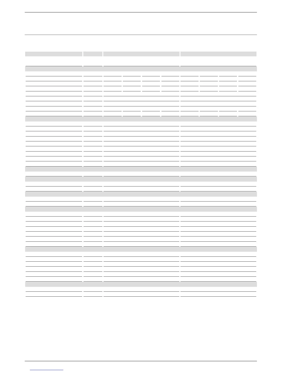
10.4 Data table
DHC-E 8/10 DHC-E 12
224201
234450
230628
234451
Electrical details
Rated voltage V 208 220 230 240 208 220 230 240
Rated output kW 5.4/7.2 6.0/8.1 6.6/8.8 7.2/9.6 9 10 11 12
Rated current A 28/35 30/50 31/39 32/40 44 46 48 50
Fuse A 30/50 40/50 40/50 40/50 60 60 60 60
Frequency Hz 50/60 50/60
Power connection 2/GRD 2/GRD
Phases 1/N/PE ~220-240V 1/N/PE ~220-240V
Cable cross-section mm² Copper -/- 6/10 6/10 6/10 - 10 10 10
Cable cross-section AWG Copper 8 - - 8 6 - - 6
Values
ON l/min > 1.0 > 1.0
ON GPM > 0.26 > 0.26
Max. permissible inlet temperature °C 55 55
Max. permissible inlet temperature °F 131 131
DHW delivery l/min 3.0-5.2 4.9-6.5
DHW delivery GPM 0.8-1.4 1.3-1.7
Δϑ if presented K 25 25
Flow rate for pressure drop l/min 1.4 1.4
Flow rate for pressure drop GPM 0.37 0.37
Connections
Water connection 1/2“ NPT 1/2“ NPT
Application limits
Max. permissible pressure MPa 1 1
Max. permissible pressure PSI 150 150
Hydraulic data
Rated capacity l 0.5 0.5
Rated capacity gal 0.13 0.13
Versions
Temperature display analogue analogue
Temperature adjustment °C 30-60 30-60
Temperature adjustment °F 86-140 86-140
Heating system Tubular heater Tubular heater
Cap and back panel Plastic Plastic
Colour white white
IP-Rating IP24 IP24
Dimensions
Height mm 360 360
Height in 14.17 14.17
Width mm 200 200
Width in 7.88 7.88
Depth mm 110 110
Depth in 4.33 4.33
Weights
Weight kg 2.7 2.7
Weight lb 5.9 5.9
f Suitable for supply with up to 131 °F / 55 °C
f Tankless water heaters are considered a non-continuous load
f Conductors should be sized to maintain a voltage drop of less than
3 % under load
 Loading...