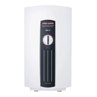
The Stiebel Eltron DHC-E is a tankless electric water heater designed for heating domestic hot water. Unlike conventional storage-type water heaters, it does not store hot water but heats it instantaneously as water flows through the appliance. This design eliminates standby losses, offering greater energy efficiency.
The DHC-E series is suitable for various applications, including supplying one or multiple hand washing sinks, a kitchen sink, or cabins with flow restriction at the shower head. For whole apartment and house applications, a combination of two DHC-E units can be used, and special installation instructions are available for such setups. The appliance is recommended for all areas where the ground water temperature is likely to exceed 65 °F (18 °C) year-round.
Function Description
The DHC-E water heater electronically controls the input of heat into the water, allowing it to deliver any water temperature between 86 °F (30 °C) and 140 °F (60 °C). Users can set the desired temperature using a knob located on the front cover of the appliance. If the "Power" light flashes during operation, it indicates that the water flow rate exceeds the appliance's heating capacity. In such cases, reducing the hot water flow rate will allow the appliance to achieve the set point temperature. The maximum temperature is electronically limited to 140 °F (60 °C).
The DHC-E 8/10 model offers adjustable output power in two stages. In its factory-delivered condition, it is set to 7.2 kW at 240 V. The output power can be selected as either 7.2 kW at 240 V or 9.6 kW at 240 V by setting a coding plug on the appliance. The selected output power should be marked on the type plate with a permanent marker.
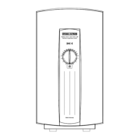
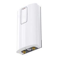
The appliance must be installed in a vertical position with the water fittings pointing downward. It should not be installed in locations where it would routinely be splashed with water to prevent electric shock. Installation should be in a frost-free area; if frost may occur, the appliance should be removed before freezing temperatures set in. A minimum of 5 inches of clearance on all sides is required for servicing.
Usage Features
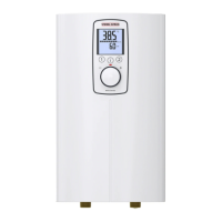
To operate the DHC-E, users adjust the water temperature using the knob on the front cover. The appliance features an LED diagnostic system, referred to as "traffic lights," to indicate its status:
- Green light flashing: The appliance is supplied with power.
- Yellow light illuminated: The appliance is actively heating water.
- Red light illuminated: Indicates a fault.
Before initial operation, the hot water faucet should be opened for a few minutes until water flow is continuous and all air is purged from the water pipes. The appliance's plastic cover must be installed before the circuit breaker is turned on. After turning on the circuit breaker, the temperature selector should be rotated clockwise and anti-clockwise to calibrate the set value transducer. Once the desired water temperature is set, hot water should be run for about twenty seconds until the temperature stabilizes. Users should check the water temperature by hand to ensure it is not too hot and reduce it if necessary.
For safety, a setting of 108 °F - 116 °F (42 - 47 °C) is recommended for most applications. The maximum temperature can be limited to 109 °F (43 °C) by connecting the lead of the electronic temperature control to a specific position (A2) during installation.
Maintenance Features
The Stiebel Eltron tankless water heaters are designed for a very long service life, with actual life expectancy varying based on water quality and usage. The appliance itself does not require any regular maintenance.
However, to ensure consistent water flow, it is recommended to periodically remove scale and dirt that may build up at the faucet's aerator, the filter screen within the appliance, or in the shower head. This is the only part of the appliance serviceable by a lay person. In case of any other malfunction, a licensed plumber or electrician should be contacted.
Troubleshooting common issues:
- No hot water: Check if the circuit breaker is off (turn it on) or if the safety thermal cut-out has tripped (reset it). Also, ensure there is sufficient flow rate to activate the appliance; if not, clean the faucet aerator or shower head.
- Water not hot enough: This can be caused by a clogged filter screen (clean it) or a water flow that is too high. If the water flow is too high, reduce it until the "Power" light on the front cover stops blinking. Ensure the appliance is receiving the correct voltage.
If problems cannot be resolved, the contractor who installed the appliance should be notified. Stiebel Eltron provides technical assistance and can often resolve issues over the phone. When contacting for support, providing the serial number from the type plate (000000-0000-000000) will facilitate and speed up the enquiry.