12 | DHF C-AU www.stiebel-eltron.com
INSTALLATION
Specication
15. Specification
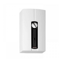
15.1 Dimensions and connections
17
30
67
320
15
370
140
220
≤12
35
130
100
141
c01
c06
32
b02
383
D0000043273
b02 Entry electrical cables I
c01 Cold water inlet Male thread G 1/2 A
c06 DHW outlet Male thread G 1/2 A
Alternative connection options
17
30
67
35
b02
b03
D0000043275
b02 Entry electrical cables I
b03 Entry electrical cables II
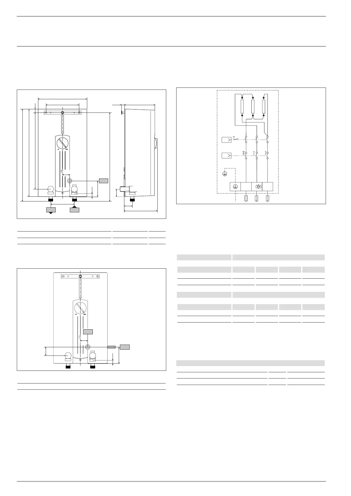
15.2 Wiring diagram
3/PE ~ 400 V
T
Q
L
LL
L
I>
L
PE L
3
3’
2
2’
1
1’
85�02�02�0007
15.3 DHW output
The DHW output is subject to the mains voltage, the appliance's
connected load and the cold water inlet temperature. The rated
voltage and rated output can be found on the type plate (see
chapter "Troubleshooting").
Connected load in kW 38 °C DHW output in l/min.
Rated voltage Cold water inlet temperature
400 V 5°C 10°C 15°C 20°C
13.2 5.7 6.7 8.2 10.5
15.0 6.5 7.7 9.3 11.9
Connected load in kW 50 °C DHW output in l/min.
Rated voltage Cold water inlet temperature
400 V 5°C 10°C 15°C 20°C
13.2 4.2 4.7 5.4 6.3
15.0 4.8 5.4 6.1 7.1
15.4 Pressure drop
Taps/valves
Tap pressure drop at a flow rate of 10 l/min
Mono lever mixer tap, approx. MPa 0.04 - 0.08
Thermostatic valve, approx. MPa 0.03 - 0.05
Hand shower, approx. MPa 0.03 - 0.15
Sizing the pipework
When calculating the size of the pipework, an appliance pressure
drop of 0.1MPa is recommended.

 Loading...