8 | DHF C-AU www.stiebel-eltron.com
INSTALLATION
Installation
f Fit the cold water inlet pipe and the DHW outlet pipe from
the pipework with flat gaskets to the extensions from the
appliance.
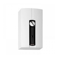
Fitting wall mounting bracket and appliance
26�02�02�0398
3
2
1
1 Wall mounting bracket
2 Threaded stud
3 Threaded bush
f Detach the wall mounting bracket from the appliance.
f Mark out the drill holes with the installation template (in the
centre section of these instructions). If the appliance is to be
installed with water connections on finished walls, also mark
out a fixing hole in the lower part of the template.
f Drill the holes and secure the wall mounting bracket with
2screws and 2rawl plugs (screws and rawl plugs are not
part of the standard delivery).
f Fit the wall mounting bracket.
f Mount the appliance on the threaded stud.
f Press the back panel firmly into place and secure it with the
threaded bush. You can compensate for a tile offset with the
nut on the threaded stud.
Installation with offset tiles
≤12
≥100
2
1
D0000043272
1 Minimum contact area of the appliance
2 Maximum tile offset
f Adjust the wall clearance with the nut on the threaded stud.
Press the back panel firmly into place and secure it with the
threaded stud.
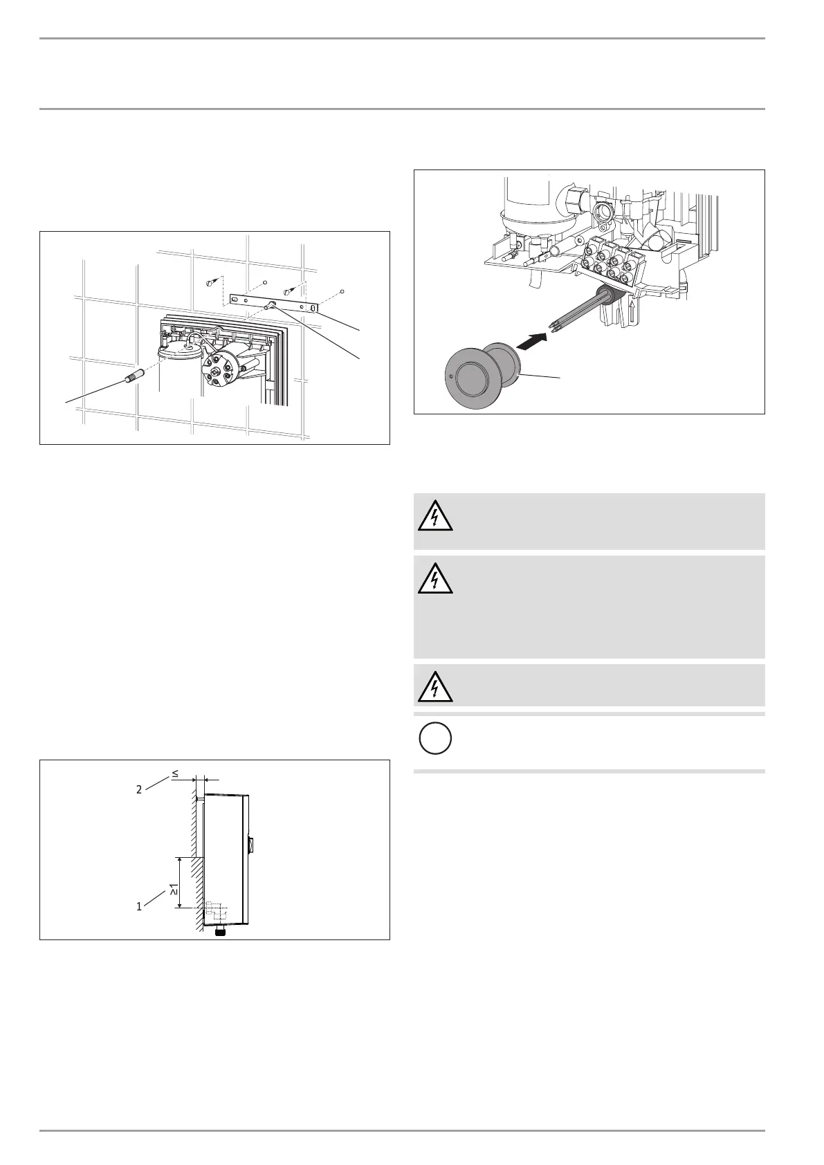
Fitting the cable grommet
1
D0000042709
1 Cable grommet
f Fit the cable grommet.
Making the electrical connection
WARNING Electrocution
Carry out all electrical connection and installation work
in accordance with relevant regulations.
WARNING Electrocution
Connection to the power supply is only permissible in the
form of a permanent connection in conjunction with the
cable grommet. Ensure the appliance can be separated
from the power supply by an isolator that disconnects all
poles with at least 3mm contact separation.
WARNING Electrocution
Ensure that the appliance is earthed.
!
Material losses
Observe the type plate. The specified voltage must match
the mains voltage.
f Connect the power cable to the mains terminal (see chapter
"Specification/ Wiring diagram").

 Loading...