140
220
≤12
35
130
100
141
c01
c06
32
b02
383
D0000043273
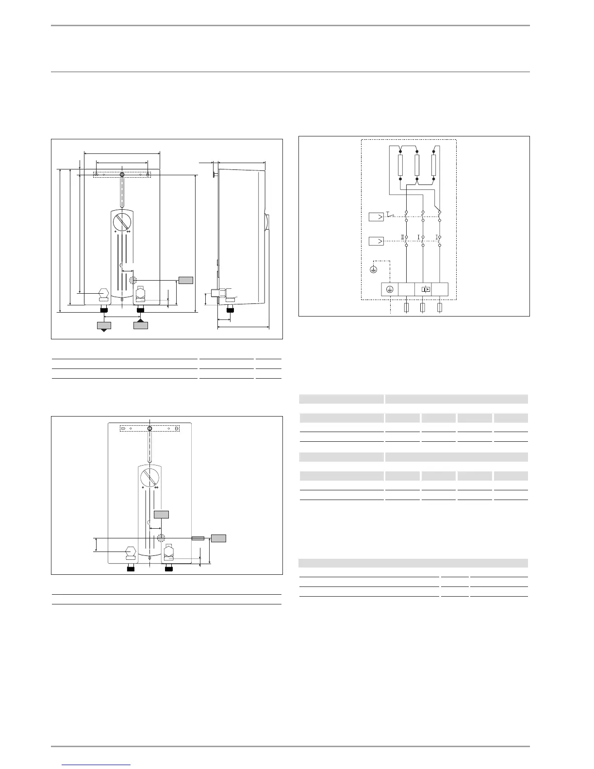
b02 Entry electrical cables I
c01 Cold water inlet Male thread G 1/2 A
c06 DHW outlet Male thread G 1/2 A
Alternative connection options
17
30
67
35
b02
b03
D0000043275
b02 Entry electrical cables I
b03 Entry electrical cables II
15.2 Wiring diagram
3/PE ~ 400 V
T
Q
L
LL
L
I>
L
PE L
3
3’
2
2’
1
1’
85�02�02�0007
15.3 DHW output
DHW output is subject to the mains voltage, the appliance's con-
nected load and the cold water inlet temperature. The rated volt-
age and rated output can be found on the type plate (see chapter
"Troubleshooting").
Connected load in kW 38 °C DHW output in l/min.
Rated voltage Cold water inlet temperature
400 V 5°C 10°C 15°C 20°C
13.2 5.7 6.7 8.2 10.5
15.0 6.5 7.7 9.3 11.9
Connected load in kW 50 °C DHW output in l/min.
Rated voltage Cold water inlet temperature
400 V 5°C 10°C 15°C 20°C
13.2 4.2 4.7 5.4 6.3
15.0 4.8 5.4 6.1 7.1
15.4 Pressure drop
Taps/valves
Pressure drop at taps at flow rate of 10 l/min
Mono lever mixer tap, approx. MPa 0.04 - 0.08
Thermostatic valve, approx. MPa 0.03 - 0.05
Hand shower, approx. MPa 0.03 - 0.15
Sizing the pipework
When calculating the size of the pipework, a pressure drop for the
appliance of 0.1MPa is recommended.
 Loading...