INSTALLATION
Preparation
ENGLISH
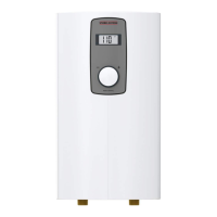
www.stiebel-eltron-usa.com DHX 15 Select | 11
10. Preparation
10.1 Installation site
!
Material losses
Install the water heater in a room that is free from the risk
of frost.
f Install DHX in a frost free area. If frost may occur, remove the
unit before freezing temperatures set in.
f Always install the water heater vertically with plumbing fittings
pointing downward. Install the water heater near the draw-off
point to minimize pipe runs and thermal losses.
f Taps: Do not use open vented or non-pressurized taps.
The water heater is suitable for under-sink and over-sink installa-
tion.
Typical under-sink installation
D0000089950-a
6
5
1
3
2
7
4
1 Electrical junction box
2 ½˝ water supply line for faucet installation
3 Shut-off valve
4 Cold water supply
5 Sink
6 Cold valve (right)
7 Hot valve (left)
Note
f Install the water heater flush to the wall. The wall
must have sufficient load bearing capacity.
10.2 Minimum clearances
Ý
Ý
Ý
Ý
D0000079442
f Maintain the minimum clearances to ensure trouble-free oper-
ation of the water heater and facilitate maintenance work.
11. Installation
Factory default settings All DHX Models
Internal temperature limit 140 °F (60 °C)
11.1 Standard wall-mounted installation
11.1.1 Preparing the power cable
4Ǭ–5ǩÝ (125–130 mm)
D0000094559-b
f Prepare the power cable.
11.1.2 Mounting instructions
f Install DHX as close as possible to the hot water draw-off point,
for example, directly underneath the sink.
f Install DHX in a frost free area. If frost may occur, remove unit
before freezing temperatures set in.
f Observe minimum clearances on all sides to ensure unob-
structed servicing if necessary.
f Remove plastic cover by loosening the screw on the bottom.
Lift cover off from the bottom.
D0000094555-b
f Mark the 2drill holes, referencing their position using the
water heater rear panel as a guide.
f Set water heater rear panel aside and drill the 2 marked holes.
 Loading...