28 | SHW S www.stiebel-eltron.com
INSTALLATION
Specication
SHW 400 S
75
55
1763
375
865
750
i18
c03
45°
45°
h43
i01
c01
c10
b02
b03
540
a43
c06
D0000017594
SHW 400 S
a43 Appliance Pitch circle diameter of feet mm 540
a45 Feet fixing hole Diameter mm 19
b02 Entry electrical cables I Diameter PG 16
b03 Entry electrical cables II Diameter PG 13.5
c01 Cold water inlet Male thread G 1 A
c03 Cold water inlet pipe
Male thread G 1 A
Torque Nm 100
c06 DHW outlet Male thread G 1 A
c10 DHW circulation Male thread G 1/2 A
h43 Thermometer Diameter mm 14.5
i01 Flange
Diameter mm 210
Pitch circle diameter mm 180
Screws M12
Torque Nm 55
i18 Protective anode Female thread G 3/4
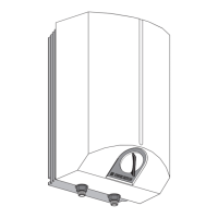
Appliance sectional view
c03
h43
i01
c01
c10
b02
b03
c06
D0000035576
16.2 Wiring diagrams and connections
1
II
3
I
2
2
1
5
4
3
6
26�02�79�0060
1 Circuit breaker in the control panel
2 Pushbutton for rapid heating
3 High limit safety cut-out
4 Temperature controller
5 Contactor
6 Heating element, 2 kW ~ 230 V each
 Loading...