iNSTallaTiON
Installation
24 | WWK222-302 H www.stiebel-eltron.com
D0000056083
1
2
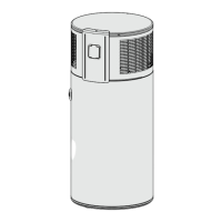
1 Strain relief
2 Terminal X3
Prepare the cables in such a way that each cable terminates
with a wire ferrule.
Push the cables through one of the cable entries in the appli-
ance casing.
Route the cables through the strain relief.
Connect the cables to X3.
Example 1: Power supply utility signal with its own phase
X0
2
L
L
N
N
PE
PE
L
N
PE
GNYE
BU
BN
1
1
2
X3
2
3
3
1
1
2
L1 / L2 / L3
N
EVU
D0000059154
EVU Power supply utility
BN Brown
BU Blue
GNYE Green/yellow
Example 2: Photovoltaic signal via on-site relay and phase
routed outside the appliance
Note
The relay in the inverter must meet the following re-
quirements:
- Potential-free relay (240VAC / 24VDC, 1A) with
N/O contact
- Adherence to safety regulations and standards for
safety extra low voltage
- The switching output must be able to be pro-
grammed such that the relay contact closes or opens
if certain limits are exceeded or undershot (inverter
output level).
If necessary, check with the inverter manufacturer wheth-
er the product meets the stated criteria.
X0
2
L
L
N
N
PE
PE
L
N
PE
GNYE
BU
BN
1
1
2
1
X3
2
3
3
1
1
2
D0000059155
1 Inverter (floating contact)
BN Brown
BU Blue
GNYE Green/yellow
The inverter power feed is usually located at a central distribution
point (e.g. in the main fuse box).
10.4 Assembling the appliance
Note
Refit the appliance cover after completing your work. See
chapter "Maintenance and cleaning/ Fitting the appliance
cover").

 Loading...