OPERATION
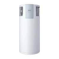
Appliance description
6 | WWK 223-303 electronic www.stiebel-eltron.com
When a hot water draw-off point is opened, the hot DHW is pushed
out of the appliance by the inflow of cold water.
The heat pump drive unit is located in the upper section of the
appliance. The DHW cylinder is located in the lower section of the
appliance. To protect against corrosion, the DHW cylinder is coated
internally with special enamel and is additionally equipped with
an impressed current anode.
The electronic control unit makes energy saving adjustments eas-
ier. Subject to the power supply and user draw-off behaviour, the
water is heated automatically to the selected set temperature.
Max. available amount of DHW
The appliance’s nominal maximum available amount of DHW is
designed for the recommended number of users with average
user behaviour.
If the amount of DHW is insufficient despite compliance with the
recommended number of users, this may be due to the following:
- The individual DHW demand is above average.
- The DHW circulation line installed as an additional option is
inadequately insulated.
- The DHW circulation pump is not controlled according to
temperature or time.
3.1 Heat pump operating principle
A closed circuit within the appliance contains refrigerant (see
"Specification/ Data table"). This refrigerant evaporates at low
temperatures.
In the evaporator, which extracts heat from the air drawn in, the
refrigerant changes from a liquid into a gaseous state. A com-
pressor draws in the gaseous refrigerant and compresses it. This
increase in pressure raises the refrigerant temperature. This re-
quires electrical energy. The energy (motor heat) is not lost, but
reaches the downstream condenser together with the compressed
refrigerant. There, the refrigerant indirectly transfers heat to the
DHW cylinder. An expansion valve then reduces the still prevalent
pressure and the cycle starts again.
Note
Following an interruption of the power supply, the
compressor operation remains blocked for at least one
minute. The PCB delays electronic starting by a minute,
during which the appliance goes through its initialising
process.
If the compressor subsequently fails to start, it may be
blocked by additional safety devices (motor overload relay
and high pressure switch). This block should lift after 1
to 10 minutes.
After the power supply has been re-established, the ap-
pliance continues to operate with the parameters that
were selected before the power supply was interrupted.
3.2 DHW heating
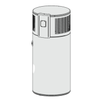
2
D0000050335
1 Cylinder top sensor
2 Integral sensor
The appliance is equipped with two temperature sensors.
- The cylinder top sensor captures the water temperature in
the upper section of the cylinder.
- The integral sensor is a temperature sensor affixed over the
entire cylinder height. The integral sensor determines the
average cylinder temperature.
The appliance display indicates the temperature in the upper sec-
tion of the cylinder, which is captured by the cylinder top sensor.
The appliance control unit uses the average cylinder temperature
captured by the integral sensor.
DHW heating is started when the available mixed water volume
decreases to the percentage of maximum mixed water volume set
in the "Charge level" parameter.
The temperature determined by the cylinder top sensor may still
correspond to the set temperature.
For information on the heat-up time, see chapter "Specification".
The calculation of the available amount of mixed water is based
on the average cylinder temperature. The amount of mixed water
is only calculated if the water temperature in the upper section of
the cylinder is higher than 40 °C.
DHW is normally heated by the heat pump of the appliance within
the application limits (see chapter "Specification/ Data table").
Electric emergency/booster heater
When the temperature in the upper section of the DHW cylinder
drops 10K below the selected set temperature, the appliance
automatically switches on the electric emergency/booster heater.
When the temperature in the upper section of the DHW cylinder
rises 2K above the selected set temperature, the appliance switch-
es off the electric emergency/booster heater.
In the event of an appliance fault, you can activate the electric
emergency/booster heater manually using the emergency mode.
See chapter "Operation/ Rapid heating key/ Emergency heating
mode".
In the event of an increase in hot water demand on a single occa-
sion, you can use the rapid heating key to activate the emergency/
booster heater manually for one-off heating in addition to the
heat pump. See chapter "Operation/ Rapid heating key/ Rapid/
comfort heating".
 Loading...