WORKSHOP MANUAL
EDITION
PAGE
34 /
124
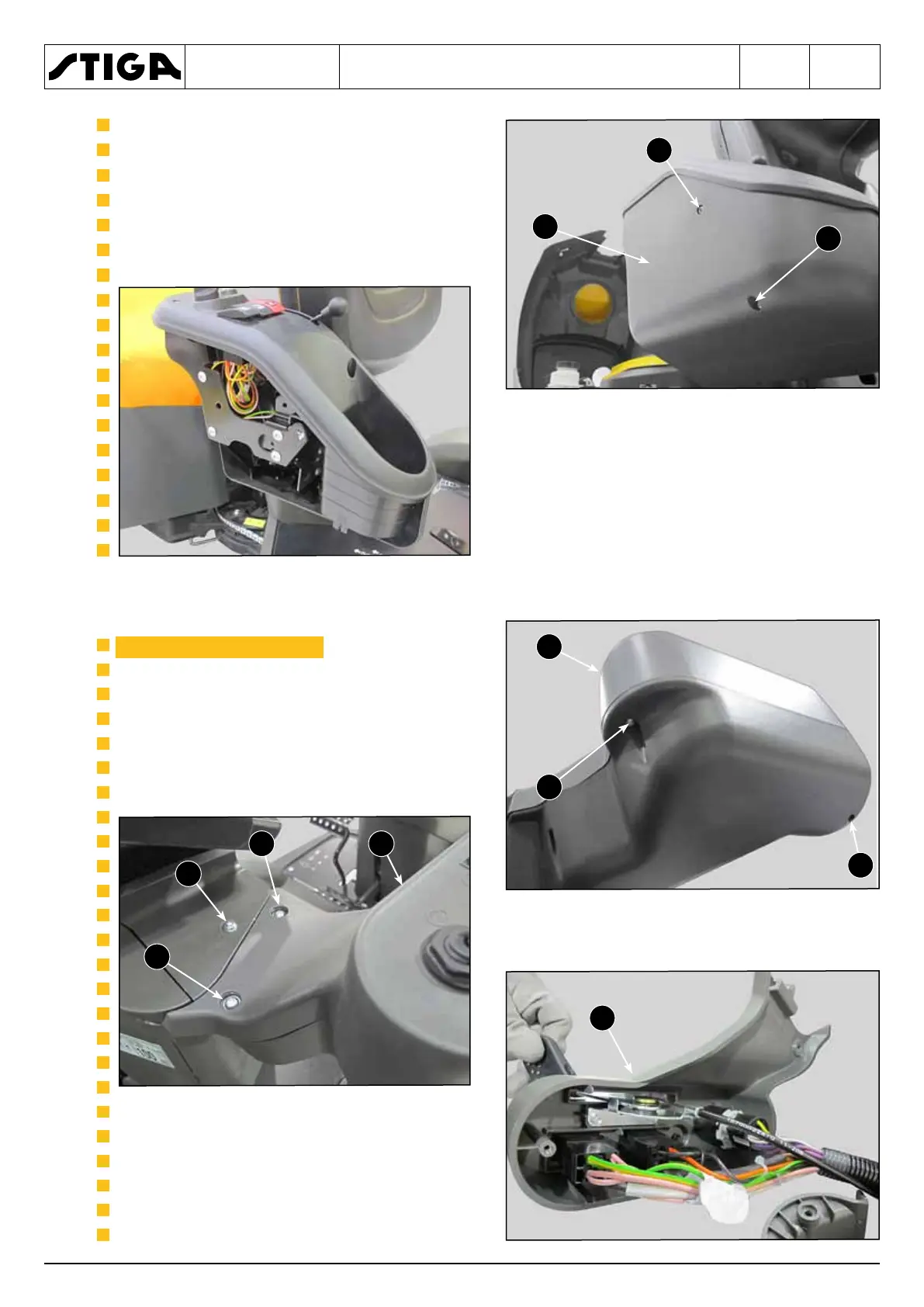
2. From the right side, unscrew the two front
screws (2) and remove the right casing (3)
to access the engine control levers and the
electrical components.
When assembling, perform the steps de-
scribed above in reverse order.
▶▶
1. Unscrew the two lower screws (1).
2. Unscrew the three upper screws (1).
3. Tilt the top panel (3) to access the engine
control levers and the electrical compo-
nents.
When assembling, perform the steps de-
scribed above in reverse order.
 Loading...