ENGLISH
EN
Locking:
1. Depress the pedal (2) fully.
2. Move the inhibitor (3) up.
3. Release the pedal (2).
4. Release the inhibitor (3).
Unlocking:
Press and release the “clutch-brake” pedal.
2.5 Driving-service brake
(4, Compact HST)
The pedal (4) determines the gearing ratio between
the engine and the drive wheels (= the speed).
When the pedal is released, the service brake is ac-
tivated.
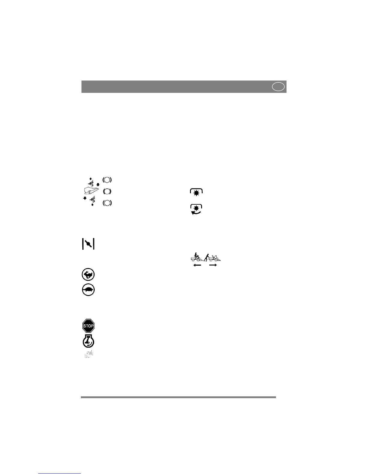
1. Press the pedal forward –
the machine moves forward.
2. No load on the pedal – the ma-
chine is stationary.
3. Press the pedal backward –
the machine reverses.
4. Reduce the pressure on the
pedal – the machine brakes.
2.6 THROTTLE/CHOKE CONTROL (5)
A control for setting the engine speed and to choke
the engine when starting from cold.
1. Choke – for starting a cold engine. The
choke is located in the top of the groove.
Avoid operating the machine in this
position, taking care to move the control
to full throttle (see below) when the
engine is warm.
2. Full throttle – when the machine is in
operation, full throttle should always be
used.
3. Idling.
2.7 IGNITION LOCK (6)
Ignition lock used for starting/stopping the engine.
Four positions:
1. Stop position – the engine is short-
circuited. The key can be removed.
2/3. Operating position.
4. Start position – the electric start motor
is activated when the key is turned to the
spring-loaded start position. Once the
engine has started, let the key return to
operating position 2/3.
2.8 GEAR LEVER (7, Compact)
A lever for selecting one of the five forward gears
in the gearbox (1-2-3-4-5), neutral (N) or reverse
(R).
The clutch pedal must be kept pressed in when
changing gear.
NOTE! You must make sure the machine is quite
stationary before changing from reverse to forward
gear or vice versa. If a gear does not engage
immediately, release the clutch pedal and then
press it in once again. Engage the gear once again.
Never force a gear in.
2.9 POWER TAKE-OFF (8)
A lever for engaging and disengaging the power
take-off for operating front-mounted accessories.
Two positions:
1. Lever in forward position – power take-
off disengaged.
2. Lever in backward position - power
take-off engaged.
2.10DISENGAGING LEVER (9,
Compact HST)
A lever for disengaging the variable transmission.
Enables the machine to be moved by hand without
the help of the engine. Two positions:
1. Lever moved back –
transmission engaged for normal
operation.
2. Lever moved forward –
transmission disengaged. The
machine can be moved by hand.
The machine may not be towed over long distances
or at high speeds. The transmission could be
damaged.
 Loading...