•
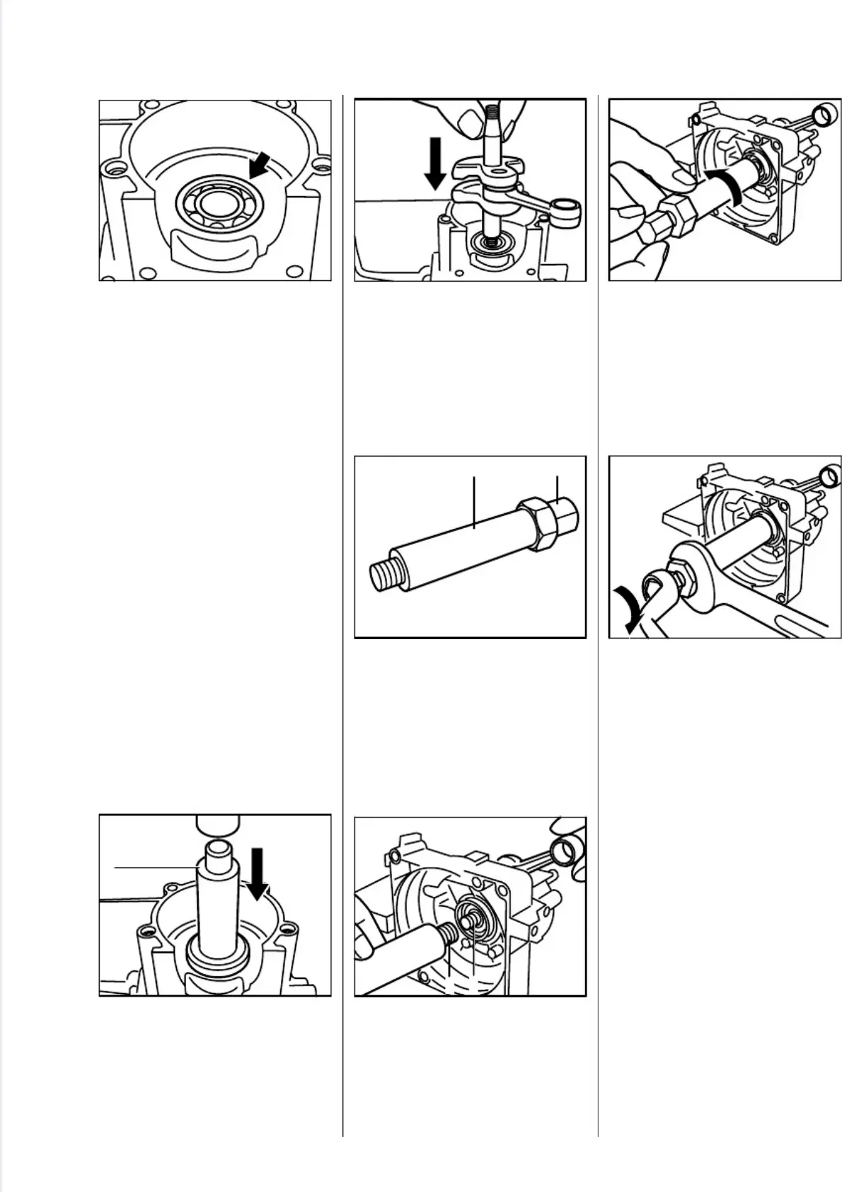
Fit ball bearing in crankcase by
hand and push it home as far as
stop.
Note:
This operation must be
carried out very quickly because
the bearing absorbs heat immedi-
ately and begins to expand.
•
If it is not possible to heat the
clutch side of the crankcase, use
press arbor (1) 4119 893 7200 to
press in the ball bearing as far
as stop.
•
Position the straight stub of the
crankshaft in the bearing at the
clutch side of the crankcase.
•
Screw spindle (1) of installing
tool 5910 890 2202 fully into the
sleeve (2) (left-hand thread).
•
Hold the crankshaft steady and
screw the spindle (1) clockwise
onto the stub (2) as far as stop.
•
Hold the spindle steady and
rotate sleeve counterclockwise
until it butts against the ball
bearing.
•
Hold the sleeve steady and
rotate spindle clockwise until the
crankshaft butts against the ball
bearing.
Important:During this process
the connecting rod (without
piston) must point towards the
cylinder flange.
- Hold the crankshaft steady and
unscrew spindle from the stub.
- Apply a thin coating of sealant to
crankcase mating face - see
13.2.
Important:Follow manufacturer’s
instructions.
2
5
0
R
A
0
7
3
V
A
2
5
0
R
A
0
7
7
V
A
2
5
0
R
A
0
7
5
V
A
3
9
2
R
A
0
4
4
2 1
V
A
2
5
0
R
A
0
7
8
V
A
2
5
0
R
A
0
7
4
1
V
A
2
5
0
R
A
0
7
6
21
V
A
FS 120, 200, 300, 350, 400, 450, FR 350, 450 21
 Loading...