5 Preparing Trimmer for
Operation
5.1 Preparing the Brushcutter for
Operation
The following steps must be performed before
commencing work:
► Ensure that the following components are in
safe condition:
–
Brushcutter, 4.6.1.
–
Deflector, 4.6.2.
–
Mowing head or metal cutting attachment,
4.6.3 or 4.6.4.
►
Clean the brushcutter,
15.1.
►
Fit the carrying ring, 6.1.
►
Mount the loop handle, 6.2.
► Select combination of cutting attachment,
deflector and carrying system, 20.
►
Mount the deflector, 6.4.1.
► If you are using a universal deflector together
with a mowing head: Fit the skirt and line limit‐
ing blade, 6.5.1.
► If you are using a metal cutting attachment:
Mount loop handle with barrier bar,
6.
► Mount mowing head or metal cutting attach‐
ment, 6.6.1 or 6.7.1.
►
Fuel the trimmer, 8.2.
►
Fit and adjust the carrying system, 7.1.
►
Adjust the loop handle, 7.2.
►
Balance the brushcutter, 7.3.
►
Check the controls, 10.1.
► If you cannot carry out this work: Do not use
your brushcutter and contact your STIHL
dealer for assistance.
6 Assembling the Trimmer
6.1 Fitting the Carrying Ring
► Shut off the engine.
► Hold the carrying ring (1) against the drive
tube (2) and then press it into position.
► Fit the nut (4).
► Insert and tighten down the screw (3) firmly.
The carrying ring need not be removed again.
6.2 Mounting the Loop Handle
► Shut off the engine.
► Fit the clamp (4) in the loop handle (3).
► Place the loop handle (3) with clamp (4) on the
drive tube (5).
► Fit washers (2) on the screws (1).
► Hold the clamp (6) against the drive tube (5).
► Insert screws (1) through holes in loop handle
(3) and clamps (4 and 6).
► Fit and tighten down the nuts (7) firmly.
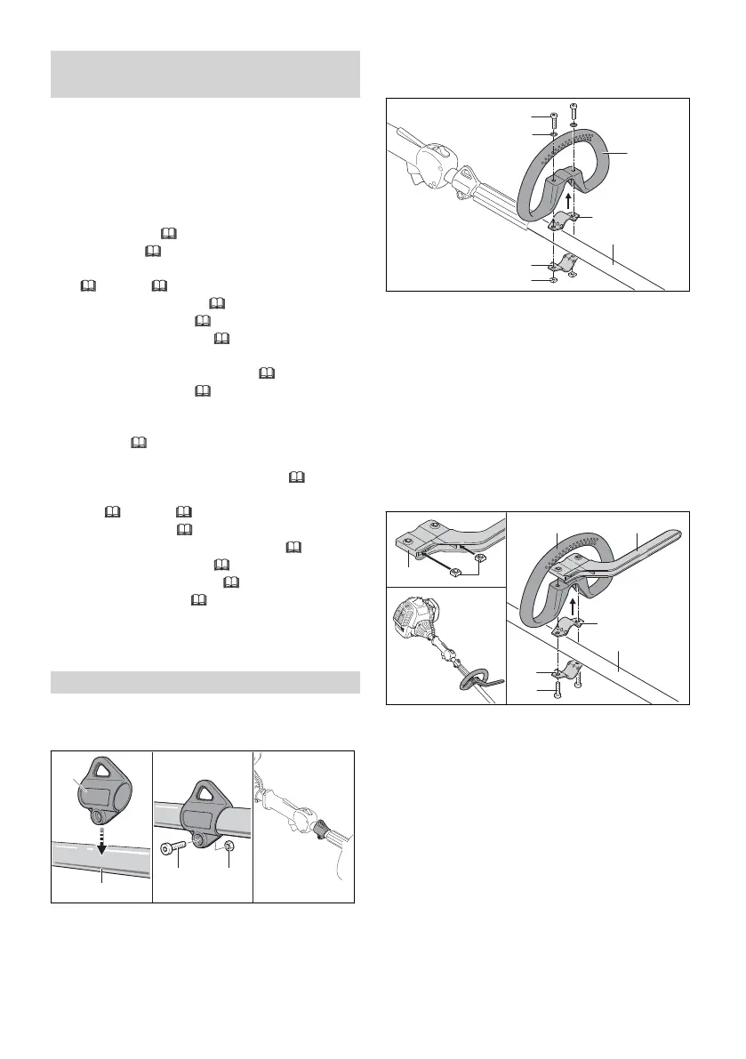
6.3 Mounting Loop Handle with
Barrier Bar
► Shut off the engine.
► Insert nuts (2) in the barrier bar (1) so that the
holes line up.
► Fit the clamp (5) in the loop handle (3).
► Place the loop handle (3) with clamp (5) and
barrier bar (4) on the drive tube (6).
► Hold the clamp (7) against the drive tube (6).
► Insert and tighten down the screws (8) firmly.
6.4 Mounting the deflector
6.4.1 Mounting the Deflector
► Shut off the engine.
5 Preparing Trimmer for Operation English
0458-891-0101-A 11
 Loading...