63FS 240 C, FS 260 C, FS 360 C, FS 410 C, FS 460 C-M
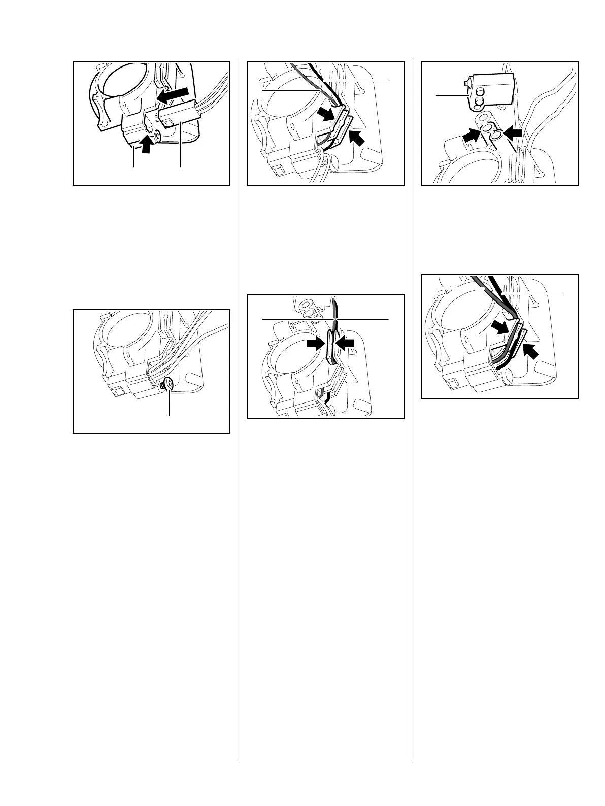
: Orient diagnostic connector (1)
so that the tab faces the
recess (arrow)
: Push the diagnostic
connector (1) into the bushing (2)
as far as it will go
: Insert and tighten screw (1) – firm
seating of the diagnostic
connector is ensured
5904RA176 TG
12
5904RA177 TG
1
Insert the thin leads of the
switchgear first.
: Press red lead (1) and black
lead (2) as far as they will go into
the guides (arrows) on the plug
Run the black lead under the red
lead – for left guide, see illustration
: Press black lead (1) and red
lead (2) as far as they will go into
the guide that is offset by
90° (arrows)
5904RA178 TG
1
2
5904RA179 TG
2 1
: Insert switchgear (1) with the
pegs in the mounts (arrows)
– Insert and tighten down the screw
Run the thick leads to the ignition
module over the thin leads.
: Press red lead (1) and black
lead (2) as far as they will go into
the guides (arrows) on the plug
5904RA180 TG
1
5904RA181 TG
1
2
 Loading...