Hardware layout and configuration UM2407
26/49 UM2407 Rev 3
6.6.2 Push-buttons
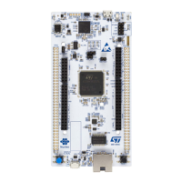
B1 USER (blue button): the user button is connected to the I/O PC13 by default (tamper
support: SB51 ON and SB58 OFF) or PA0 (wake-up support: SB58 ON and SB51 OFF) of
the STM32H7 series microcontroller.
B2 RESET (black button): this push-button is connected to NRST and is used to reset the
STM32H7 series microcontroller.
6.6.3 MCU voltage selection: 1V8/3V3
The STM32H7 Nucleo-144 board offers the possibility to supply the STM32H7 series
microcontroller with 1.8
V or 3.3 V. JP5 is used to select the VDD_MCU power level.
• Place the JP5 jumper on 3V3 to supply the MCU with 3V3, connecting pins 1 and 2.
• Place the JP5 jumper on 1V8 to supply the MCU with 1V8, connecting pins 2 and 3.
6.6.4 Current consumption measurement (IDD)
The IDD jumper (JP4) is used to measure the STM32H7 series microcontroller consumption
by removing the jumper and by connecting an ammeter:
• JP4 must be ON when STM32H7 is powered with 3V3_VDD (default)
• If JP4 is OFF, an ammeter must be connected to measure the STM32H7 current. If
there is no ammeter, the STM32H7 is not powered.
Warning: On MB1364 REV.C, ‘VDD_MCU’ is also supplying Ethernet
PHY (U15) and debug voltage translation (U1 and U10).
If needed, for low power measurement (for example Standby mode), to measure only MCU
(U7) power consumption, the user must remove the following components: R4, R43, R44,
R45, R46, R47, R48, R49, R50, R51, R52, R53, R59, R61, U1, U10, U15, and SB45.
After removing these components, it becomes impossible to use Ethernet and 1.8 V debug
with STLINK-V3E.
6.6.5 Virtual COM port (VCP): LPUART/USART
The STM32H7 Nucleo-144 board enables connecting an LPUART or a USART interface to
the STLINK-V3E, or to the ST morpho and ARDUINO
®
Uno V3 connectors.
The selection is done by setting the related solder bridges (refer to Table 10 and Table 11
below).
By default the USART3 communication between the target STM32H7 and the STLINK-V3E
is enabled, to support the Virtual COM port (SB12 and SB19 ON).

 Loading...