EasyManua.ls Logo

STMicroelectronics STM8 User Manual

STMicroelectronics STM8
126 pages
To Next Page IconTo Next Page
To Previous Page IconTo Previous Page
Page #5 background imageLoading...
Page #5 background image
Hardware Tools
The list of hardware tools needed is not very long. We will obviously need a STM8 board and I prefer
a Discovery board over other boards since it comes with a built-in ST-Link programmer/debugger
hardware. If you have some other board like the ones I already showed, you will need a ST-Link
programmer. I recommend an additional ST-Link programmer apart from the one available on board.
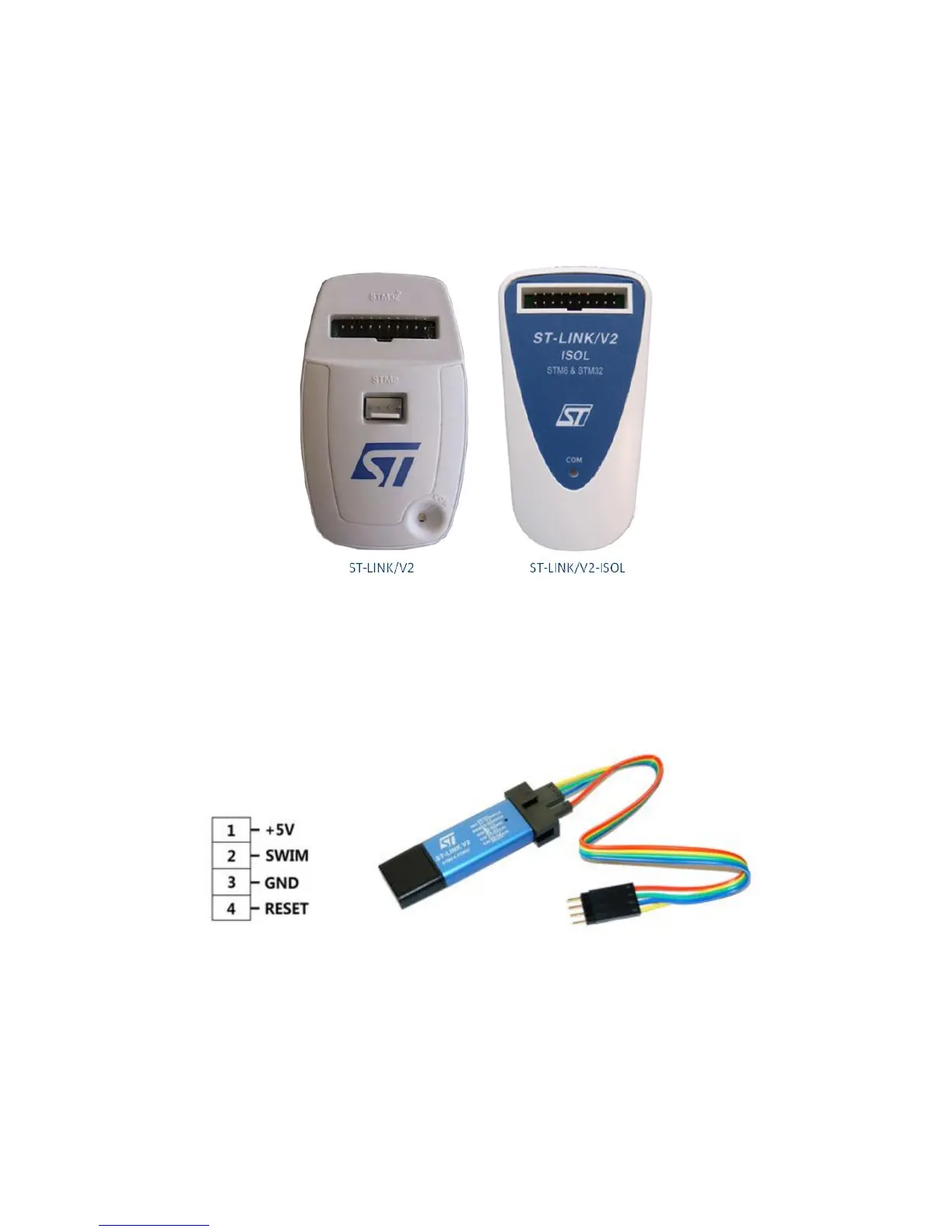
ST-Link programmers/debuggers communicate with target STM8 micros via SWIM interface. This
interface is the standard for all STM8 micros. Basically, it is a four-wire interface with two wire (VDD
and GND) being used for powering the target. The rest two are reset I/O and SWIM I/O. In the official
ST-Link V2 programmer unlike other ST-Link programmers, there is a dedicated port for SWIM
interface with STM8 inscribed near it. Cheap USB flash drive-sized ST-Links are also available in the
market and they are portable and as good as the official ones.
Apart from these we will also require some basic electronic lab stuffs like a USB-to-serial converter,
connecting/jumper wires, LEDs, buttons, various types of sensors, etc. that are typically found in a
common Arduino starter kit.
Question and Answer IconNeed help?

Do you have a question about the STMicroelectronics STM8 and is the answer not in the manual?

STMicroelectronics STM8 Specifications

General IconGeneral
ADC Resolution10-bit
CoreSTM8
Maximum Clock FrequencyUp to 24 MHz
Flash MemoryUp to 128 KB
RAMUp to 6 KB
EEPROMUp to 2 KB
Operating Voltage2.95 V to 5.5 V
Operating Temperature-40°C to +85°C or +125°C
Communication InterfacesUART, SPI, I2C
Package OptionsLQFP, TSSOP, UFQFPN, SO

Summary

Hardware Tools

Software Tools

Creating a New Code Project

Uploading Code

General Purpose Input Output (GPIO)

Clock System (CLK)

External Interrupt (EXTI)

Alphanumerical LCD

Analog-to-Digital Converter (ADC)

Analog Watchdog (AWD)

Independent Watchdog (IWDG)

Window Watchdog (WWDG)

Time Base Generation (TIM2)

Timer Interrupt (TIM4)

General Purpose Pulse Width Modulation (TIM2 PWM)

Advanced Pulse Width Modulation (TIM1 PWM)

Timer Input Capture (TIM1 & TIM2)

Serial Communication (UART)

Serial Peripheral Interface (SPI)

Inter-Integrated Circuit (I2C)

Peripheral Clock Configurations

Unlocking a Locked STM8 Chip

Related product manuals