EasyManua.ls Logo

Stora Enso CLT - Drilling and Load-Bearing Parameters; Blind-Hole Depth Specification; Steel Dowel Depth and Alignment

Default Icon
16 pages
Print Icon
To Next Page IconTo Next Page
To Previous Page IconTo Previous Page
Loading...
9 (16) CLT Lifting Guideline
Below parameters for drillings and load-bearing capacities of our standard CLT panels styles. If a panel style is not listed, then parameters for
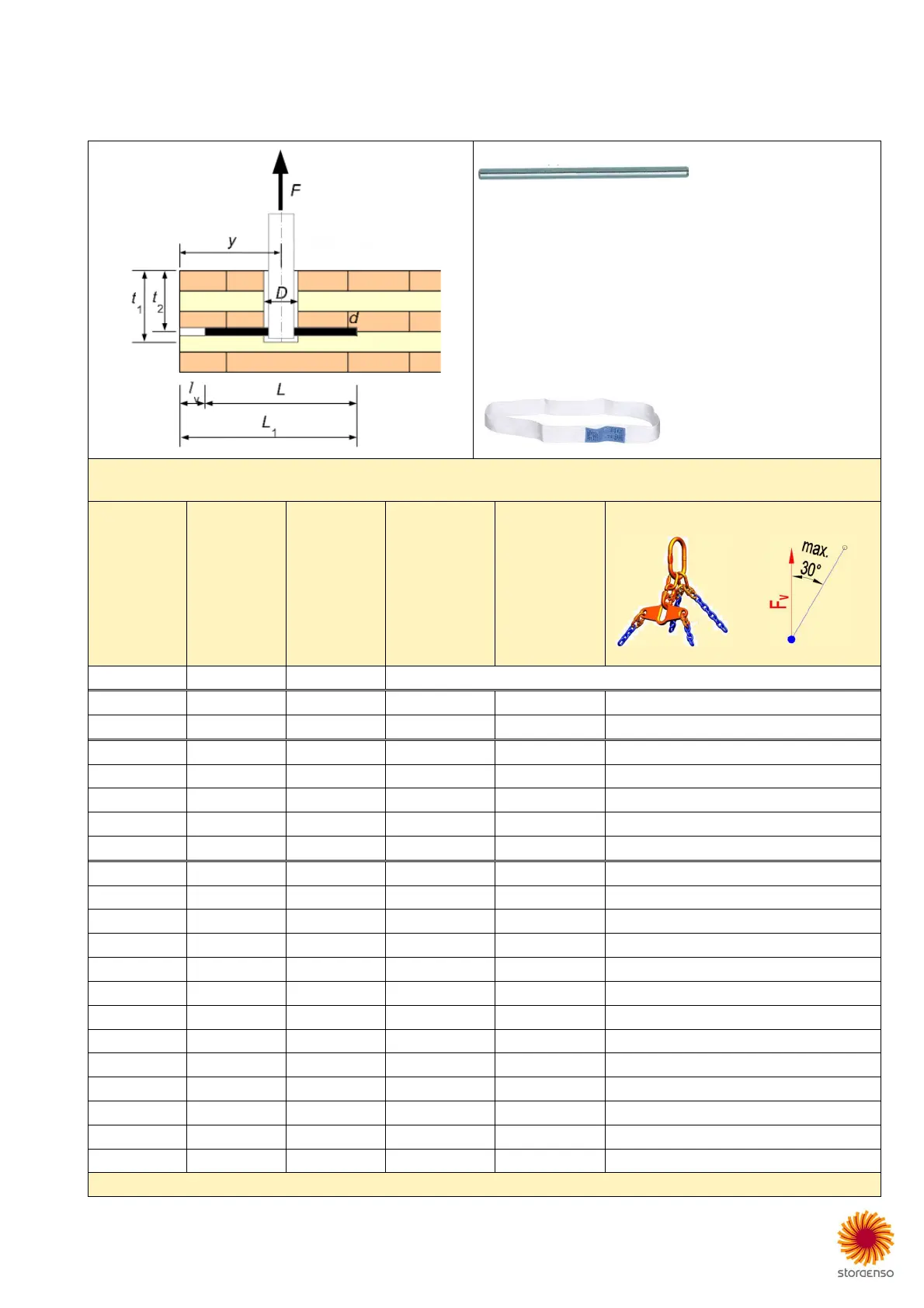
blind-hole and steel dowel must be done according to the following basic two rules:
t1 … The blind-hole should be as deep as possible but can be maximal 160 mm.
t2 … The steel dowel has to be 20 mm less deep than t1 and dowel axis should be aligned perpendicular under the layer above.
Steel dowel (d):
diameter: 16 mm
length: 300 mm
depth (t2): see table below
steel grade: S235
Blind-hole (D):
diameter 68 mm
depth (t1): see table below; max. 160 mm
Edge distance (y):
min = 200 mm
max = 340 mm
Webbing PES sling: 50x1000 mm; blue label
The lifting angle (β) is assumed to be maximal 30°.
Indicated loads are only valid for hoisting velocity up to 36 m/min = 0.6 m/s.
Product
Thickness
Structure
Blind-hole
t1
Steel dowel
t2
with load
distributor *
F
v
(kg)
CLT
60
L3s
not
possible
CLT
80
L3s
70
50
500
CLT
90
L3s
80
60
500
CLT
100
L3s
90
70
1000
CLT
120
L3s
110
90
1000
CLT
100
L5s
90
70
1000
CLT
120
L5s
100
80
1000
CLT
140
L5s
110
90
1000
CLT
160
L5s
130
110
1250
CLT
180
L5s
140
120
1250
CLT
200
L5s
-
2
150
130
1250
CLT
160
L5s
-
2
140
120
1250
CLT
180
L7s
160
140
1250
CLT
200
L5s
160
140
1250
CLT
240
L7s
160
140
1250
CLT
220
L7s
-
2
160
140
1250
CLT
240
L7s
-
2
160
140
1250
CLT
260
L7s
-
2
160
140
1250
CLT
280
L7s
-
2
150
130
1250
CLT
300
L8s
-
2
160
140
1250
CLT
320
L8s
-
2
160
140
1250
*
With
out
load distributor
(
or something
equivalent
)
indicated loads have to be reduced
at least
by
25 %.