2
OPERATION GUIDE
2-450174-030A
WWW.VARI-LITE.COM
NOTE: The material in this manual is for information purposes only and is subject to change without notice.
Strand Lighting assumes no responsibility for any errors or omissions, which may appear in this manual. For
comments and suggestions regarding corrections and/or updates to this manual, please contact the nearest
Strand Lighting oce.
PREFACE
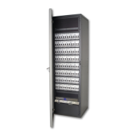
Thank you for choosing Strand C21 / EC21 Advanced Technology dimmer rack. We trust that the equipment will
meet all your dimming needs and will provide you with reliable service for many years.
Strand can assure you that every eort has been made to ensure that the equipment has been designed to
meet the highest professional standards and that dimmer racks and their components have been assembled,
inspected, and tested in accordance with our strict quality assurance program.
Should you encounter any problems or diculties with your dimmer racks, please contact the nearest Strand
service representative. For a complete list of Vari-Lite oces and service centers or visit our website (www.vari-
lite.com).
This manual describes the operation of for C21 / EC21 Advanced Technology dimmer racks. A separate Installa-
tion Guide provided with the dimmer racks describes how to install the dimmer racks and perform initial setup
procedures.
TECHNICAL ASSISTANCE
C21 / EC21 racks and dimmers require a minimum of maintenance and servicing.
For operation or technical assistance, please contact Vari-Lite or the local Authorized Service Center serving
your area.
DEFINITION OF TERMS
This manual uses the following terms throughout:
channel A device controlling a dimmer or group of dimmers. Historically, there is a physical con-
troller (such as a slider) for each channel. On most current control systems, channels are
numbers accessed by a numeric keypad. Each channel can control multiple dimmers.
circuit A connection device and wiring for powering a lighting fixture from a dimmer.
circuit ID A unique six-digit numeric identity which you can assign to each dimmer. The circuit ID
may be the same as the dimmer number, or may be a number used to indicate circuit
location, phase, channel number, etc. This feature is useful for tracking all circuits in the
architecture.
crossfade A fade that contains both an up-fade and a down-fade, or any fade where the levels of
one cue are replaced by the levels of another cue.
cue The process of recalling a preset from its memory location and putting the result on stage.
Preset, Memory, and cue are often used interchangeably.
curve The relationship between a control level and the actual dimmer output.
dimmer A device controlling power to a lighting fixture. Two lights on the same dimmer cannot be
separately controlled.
default The original factory settings.
DMX512 An ANSI communications protocol standard that describes a method of digital data trans-
mission between controllers, lighting equipment and accessories.
Ethernet A high-speed network based protocol used to transmit data from a lighting controller to a
dimmer rack using a single Ethernet cable.
fade A gradual change in stage levels from one set of intensities to another.
fade time The time it takes for dimmer levels to go from their current levels to the levels in the se-
lected preset, or DMX512 value. Each preset has its own fade time.
IGBT Insulated Gate Bipolar Transistor. IGBT dimmers are solid-state and operate silently with-
out the use of chokes and can handle a variety of load types. They reduce lamp filament
noise during dimming operation, are smaller, lighter, and generate far less neutral harmon-
ics than conventional dimmers. IGBT dimming technology provides superior overload and
short-circuit protection and operates at significantly higher rise/fall times regardless of
load size.
 Loading...